What Is Inside a Power Transformer?
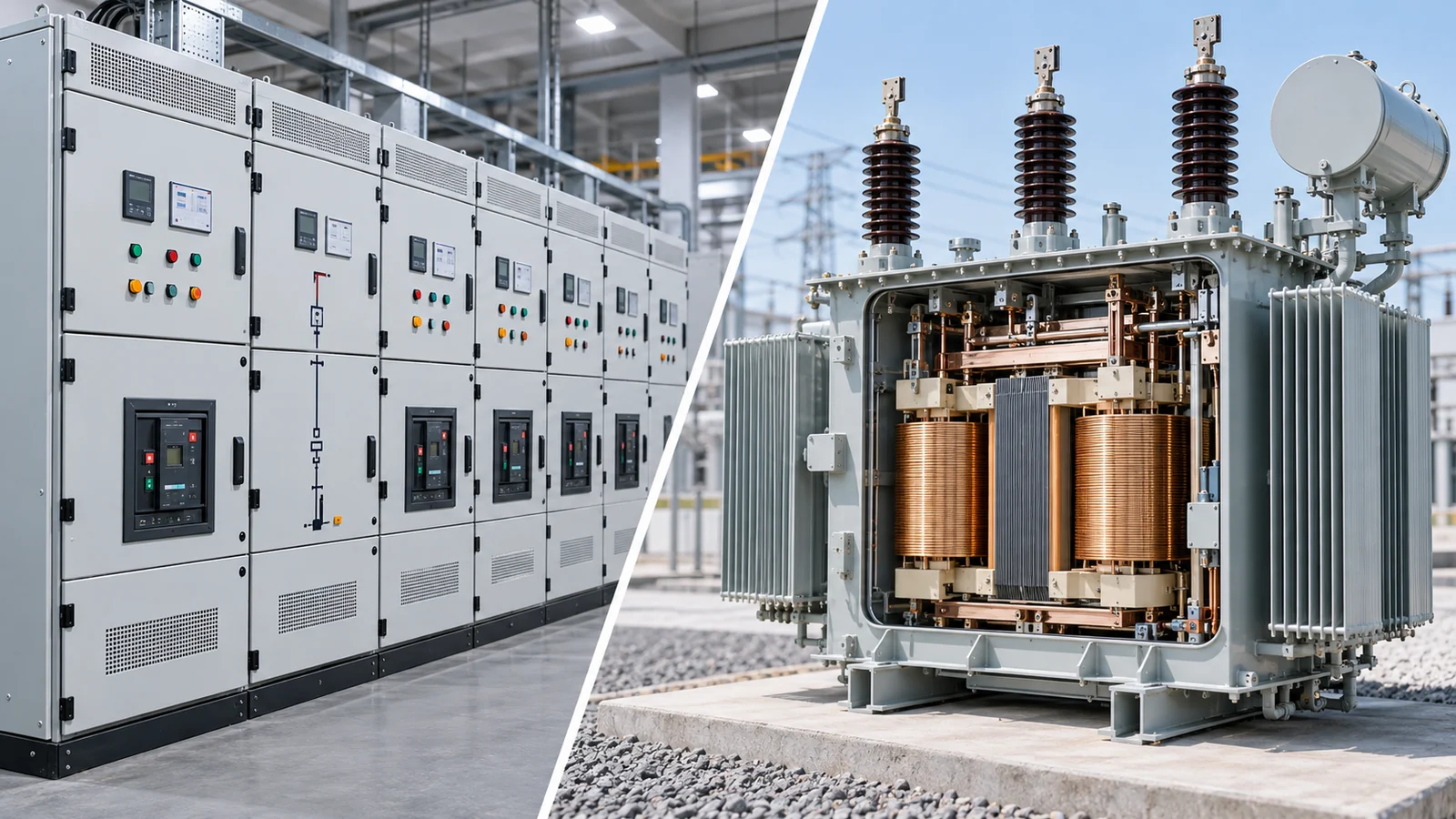
Inside a power transformer, the main active parts are the magnetic core, windings, insulation and the electrical connections between them. The core guides alternating magnetic flux, while the windings transfer electrical energy through electromagnetic induction. In an oil-immersed transformer, this active assembly is housed in a tank with insulating liquid, bushings and a cooling arrangement. Tap-changing and monitoring equipment may also be fitted, depending on the design.
Not every transformer has the same construction. Dry-type transformers use a different insulation and enclosure arrangement from oil-immersed units, and optional equipment varies by rating and duty. Understanding the components helps a buyer read an electrical specification, but it does not establish the configuration of any particular unit. For integrated distribution projects, JSGK provides a Transformer Overview as a reference alongside its substation and switchgear product families, not as proof of standalone transformer manufacturing.
The Magnetic Core: A Path for Alternating Flux
A transformer’s core provides a low-reluctance magnetic path linking the windings. It is commonly built from insulated laminations of magnetic material rather than one solid metal block. Laminations help limit eddy-current losses that would otherwise arise from changing magnetic flux. The specific core geometry, material and construction depend on the transformer design.
The core has limbs and yokes forming the magnetic circuit. Its role is to support electromagnetic coupling; it is not an electrical conductor connecting the primary circuit directly to the secondary circuit. This distinction is important because an ordinary two-winding transformer transfers energy magnetically while maintaining the insulation separation provided by its design.
Primary and Secondary Windings: Where Voltage Changes
Windings consist of insulated conductors arranged around the magnetic core. When an alternating voltage is applied to the input winding, changing flux induces voltage in the other winding. The turns relationship is central to voltage transformation, although practical operation also depends on losses, regulation and the full electromagnetic design.
In many designs the high-voltage and low-voltage windings are physically arranged to control insulation clearances, coupling, heat removal and mechanical forces. Lead connections bring the winding terminals to internal connections, bushings or tap-changing equipment as applicable. A simple ‘copper coils inside a box’ description misses the insulation, support and connection structures needed for the active assembly to perform its function.
Winding conductor material, layering, arrangement and short-circuit withstand characteristics must be verified from the specific manufacturer’s design documents. The component description here does not represent an internal construction drawing for any JSGK-branded transformer.
Internal Insulation Separates Different Electrical Potentials
Transformer insulation separates turns within a winding, adjacent windings and conductive parts at different electrical potentials. It also supports clearances between active conductors, the core and other structures. Depending on design, insulation may use solid materials, barriers, spacers, insulating liquid and controlled clearances.
The insulation system must be understood together with temperature and operating conditions. For an oil-immersed design, liquid serves electrical insulation and heat-transfer functions, alongside solid insulating materials. A dry-type unit uses a different combination of solid insulation and air or other design-specific media. These are broad construction families, not interchangeable internal layouts.
The Tank and Insulating Liquid in Oil-Immersed Designs
In a conventional oil-immersed power transformer, a metal tank encloses the core-and-winding assembly and insulating liquid. The tank provides containment and mechanical protection, and its construction is integrated with thermal expansion, pressure, sealing and cooling requirements.
The liquid performs both insulation and heat-transfer roles. It carries heat away from the active parts toward the cooling surfaces or connected cooler system. The type of liquid and its compatibility with materials and operating conditions should be confirmed for the specific design. A dry-type transformer does not have the same oil-filled main-tank arrangement.
Bushings: Electrical Connections Through the Enclosure
A bushing allows an energized conductor to pass through a grounded transformer enclosure while maintaining the necessary electrical insulation. In an oil-filled unit, bushings provide insulated interfaces between internal windings or leads and the external power system. Their ratings and construction differ by voltage and current duty.
Some designs use different types of bushings or terminal arrangements, so buyers should not assume every transformer shows the same external porcelain-looking components. The correct external connection and clearance requirements belong to the equipment drawing and project specification.
Tap Changers Adjust the Effective Winding Turns
A tap changer selects among winding connection points to adjust the transformer’s effective turns ratio and therefore its voltage relationship. Some designs use de-energized tap changing, which requires the specified out-of-service conditions. Others have an on-load tap changer designed to operate while the transformer remains energized under defined circumstances.
These are different mechanisms and operating duties. The presence, location and type of a tap changer must be verified for the actual transformer. Not every transformer uses the same tap-changing system, and knowledge of the internal parts is not an instruction to operate or service them.
Cooling Components Remove Heat from the Active Assembly
Core and winding losses produce heat. A transformer’s cooling arrangement transfers that heat away so operation remains within its designed thermal limits. An oil-immersed unit may use tank walls, radiators, fans, pumps or separate cooling equipment, depending on rating and cooling method. Not every unit includes fans or pumps.
In dry-type transformers, heat transfer depends on the particular insulation and air-cooling arrangement, sometimes assisted by fans. Oil-immersed and dry-type systems therefore cannot be compared simply by counting external cooling accessories. The specified cooling duty and operating environment govern the selection.
Conservators, Breathers and Protection Devices Are Design-Dependent
Some liquid-filled transformers use a conservator tank to accommodate changes in liquid volume. Depending on the arrangement, a breather may help manage the condition of air entering the conservator system. Other configurations use sealed or hermetically sealed construction and do not have the same conservator arrangement.
Protection and monitoring accessories can include temperature measurement, pressure-related devices, oil-level indication and gas-operated protection on designs where those devices are appropriate. Their existence is not universal. Buyers should read the approved equipment list and schematic rather than assume a textbook cutaway is a complete representation of every transformer.
Dry-Type vs. Oil-Immersed Transformers: What’s Different Inside?
The magnetic core and windings are central to both families, but insulation, enclosure and cooling differ considerably. The comparison below describes typical concepts rather than a model-specific specification.
| Feature | Dry-type design | Oil-immersed design |
|---|---|---|
| Magnetic core | Present | Present |
| Windings | Present, insulated according to design | Present, within solid/liquid insulation system |
| Insulation and cooling medium | Solid insulation and air-related cooling arrangement | Solid insulation plus insulating liquid |
| Oil-filled main tank | Not part of conventional dry-type construction | Typical |
| Radiators / liquid coolers | Not the conventional oil-cooling arrangement | May be present depending on rating |
| Conservator | Not applicable in the oil-conservator sense | Depends on sealed or conservator-type design |
JSGK’s transformer overview discusses dry-type and oil-immersed families for project selection. It should be read as a supporting reference for an integrated electrical system. It is not evidence that every transformer construction in this comparison is a verified JSGK manufacturing offering.
What Should Buyers Confirm Beyond the Internal Parts?
An understanding of transformer components helps interpret a specification, but it does not complete a quotation request. For a substation or distribution project, buyers generally need to define:
- Rated capacity and required primary/secondary voltages.
- System frequency and phase arrangement.
- Impedance and voltage-regulation requirements where specified.
- Insulation, temperature and cooling requirements.
- Installation environment and space limitations.
- Applicable equipment and project standards.
- Connection arrangement, terminals and cable interfaces.
- Required monitoring and protection interfaces.
- Single-line diagram and coordination with upstream/downstream switchgear.
- Documents and approval requirements for the proposed equipment.
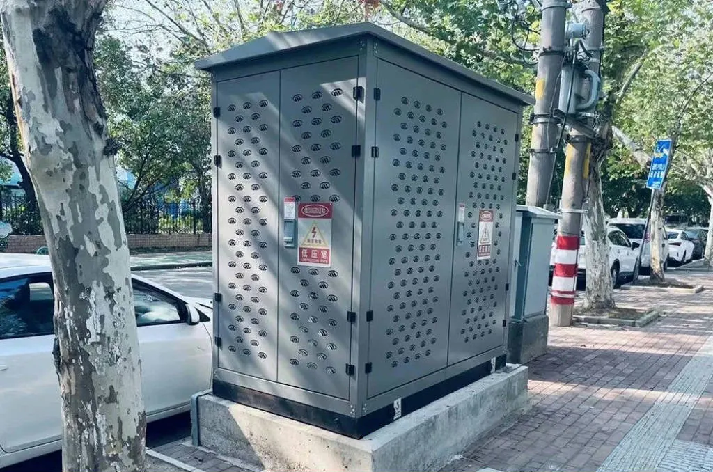
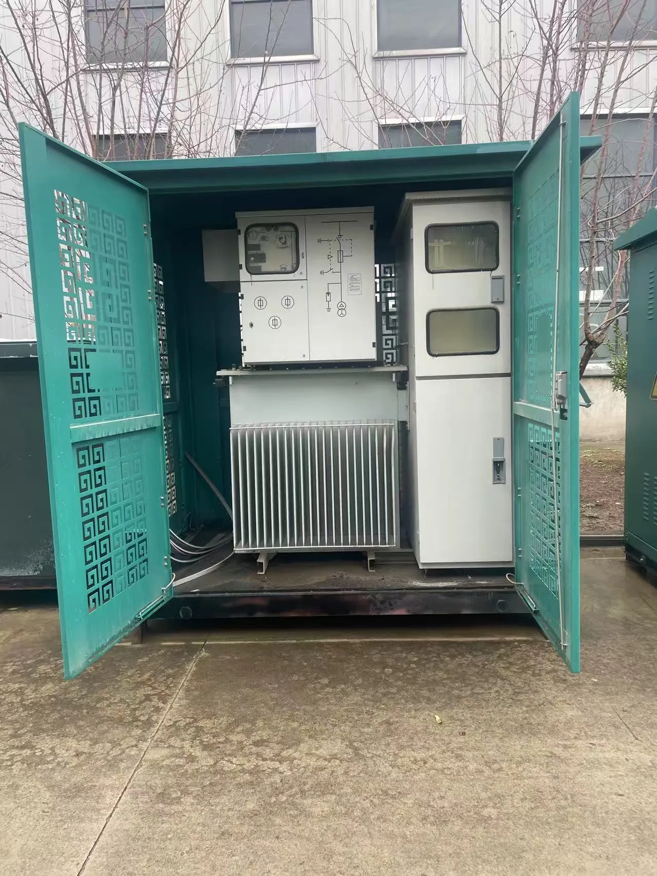
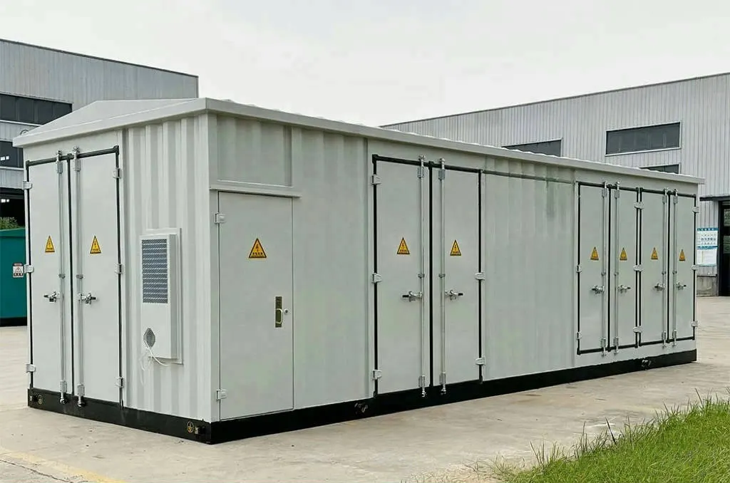
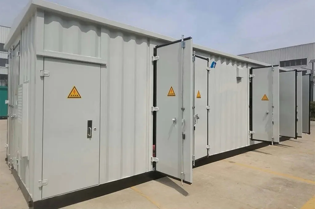
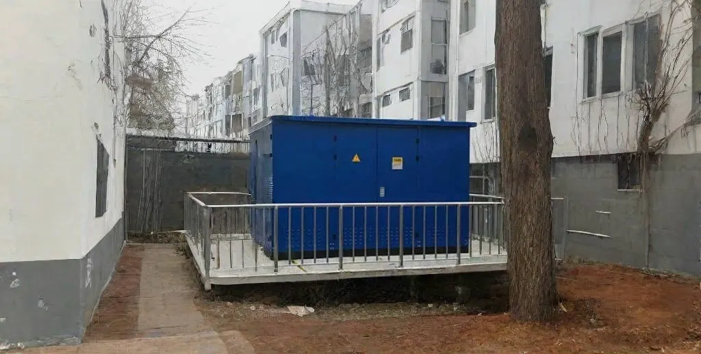
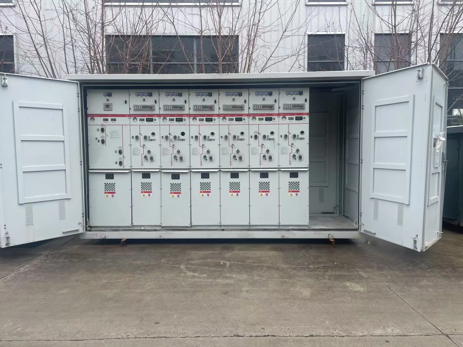
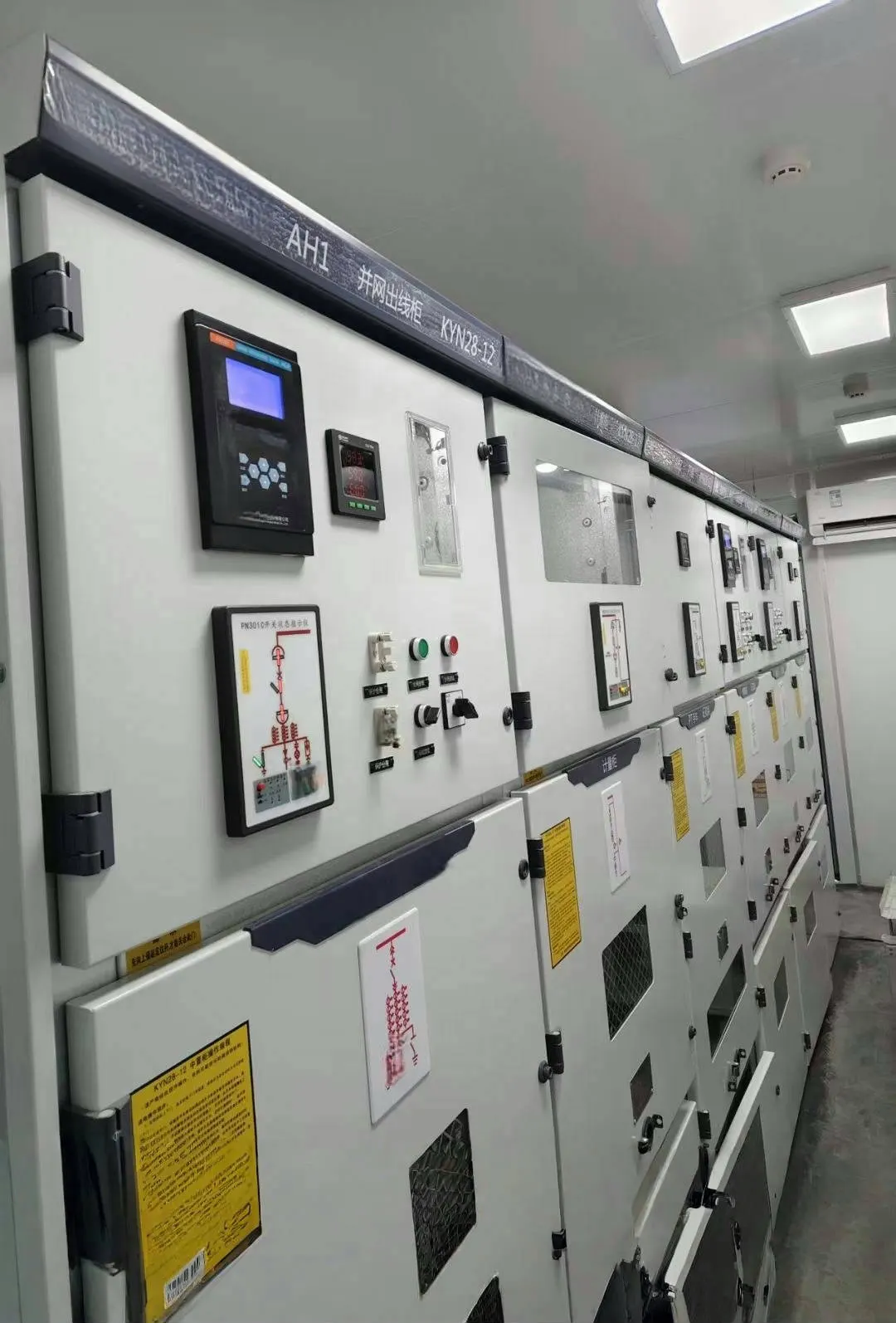
In an integrated station, transformer selection must coordinate with the system around it. The transformer changes voltage; the associated switchgear controls and protects connected circuits; the enclosure and cable layout must allow the approved equipment to be installed and maintained. JSGK’s box-type substation route provides a relevant project context, while its electrical equipment catalog shows the related distribution product families.
In short, a power transformer contains a core, windings, insulation and connections, with cooling, bushings, tap-changing and protective accessories depending on construction. Understanding those components helps define what needs to be confirmed, not what every unit automatically includes. Project buyers can discuss transformer and substation specifications with JSGK by supplying voltage, capacity, installation, connection and system-interface requirements.