What Is Electrical Switchgear? Components, Types and Functions
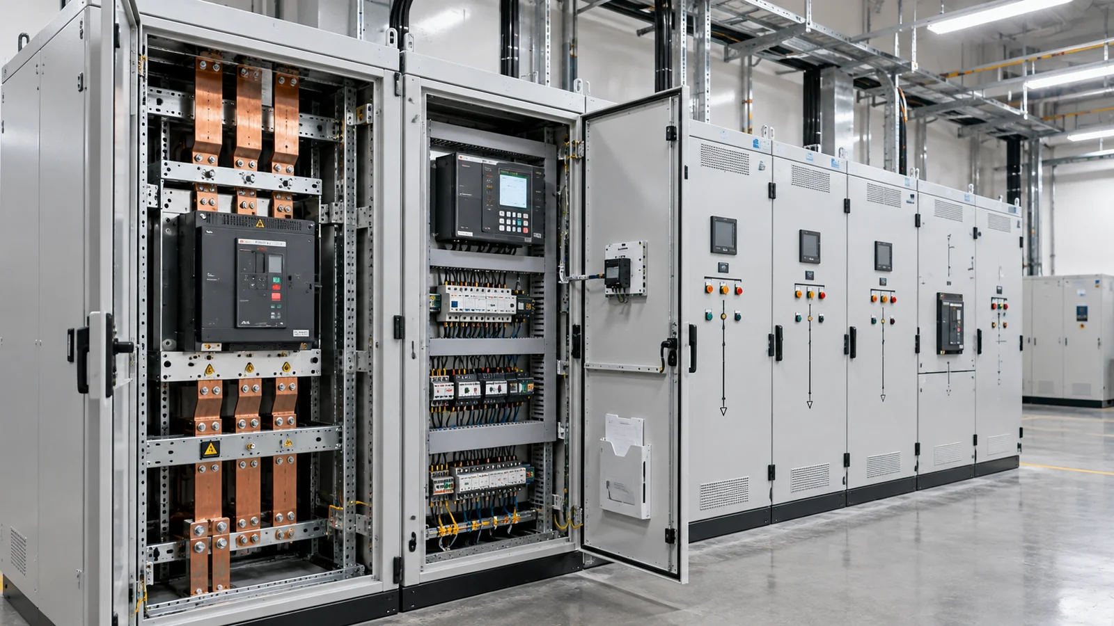
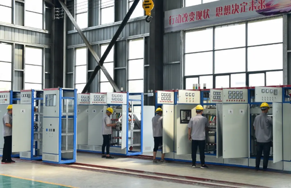
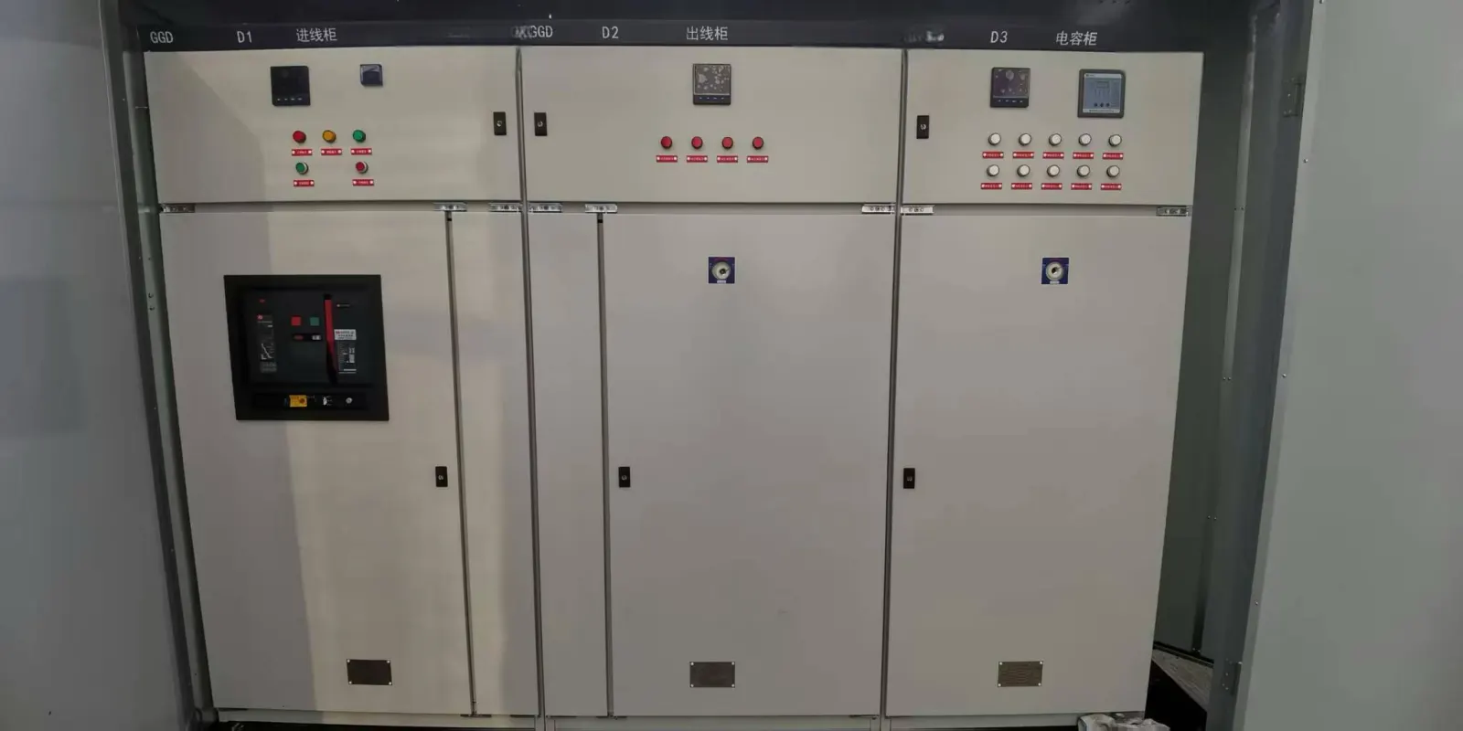
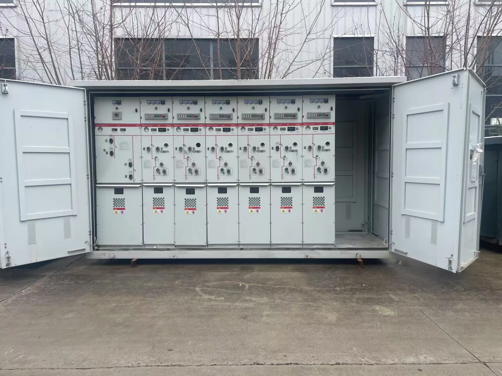
Electrical switchgear is an assembly of switching, protection, control and isolation equipment used to manage electrical circuits. Depending on the design, it may contain circuit breakers, switches, disconnectors, busbars, protective relays, instrument transformers and metering devices. Its purpose is not simply to distribute power: it also helps clear electrical faults, control feeders and establish the isolation required for maintenance. The exact arrangement varies with voltage class, installation, protection scheme and applicable standards.
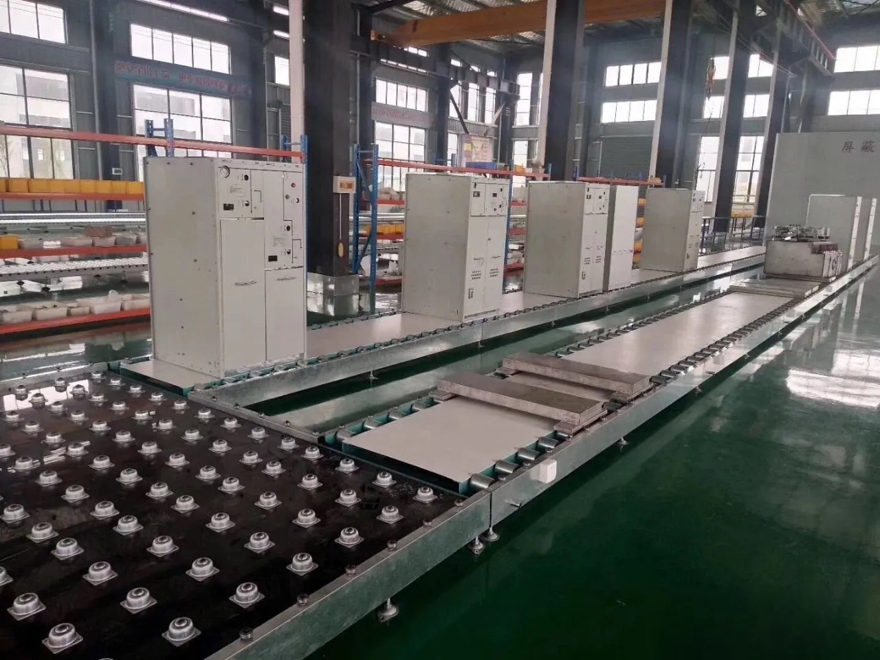
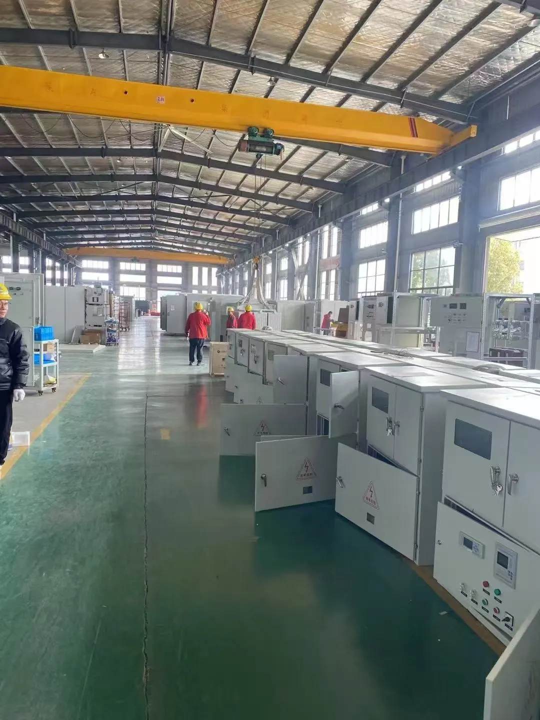
For anyone asking what is electrical switchgear, it helps to separate the system’s tasks from the physical cabinet. A circuit breaker is one component; a switchgear assembly coordinates several components to serve a defined part of a power system. JSGK presents high-voltage switchgear, low-voltage cabinets and ring main units within its electrical equipment catalog, giving project buyers product-family starting points rather than a universal configuration.
What Does Electrical Switchgear Actually Do?
Switchgear has three closely related functions: control, protection and isolation. Each function may use different devices, even when several functions are assembled in one lineup.
Control: Opening, Closing and Routing Circuits
Switching devices let operators or control systems open and close designated circuits, subject to their operating ratings. Incoming sections, bus couplers and outgoing feeders may be arranged to match the single-line diagram. A switching device suitable for normal load current is not automatically rated to interrupt a short circuit; the equipment specification must identify its duty.
Protection: Detecting and Clearing Faults
Protection functions may respond to overcurrent, short circuits, earth faults or other conditions defined by the system design. A protective relay can evaluate measurements and initiate a trip, while a suitably rated circuit breaker interrupts the fault current. Some low-voltage devices incorporate protection and interruption in one unit. Neither the existence of a relay nor a label that says ‘protected’ proves that a complete scheme has been coordinated.
Isolation: Establishing a Safe Electrical Boundary
Isolation is different from interrupting fault current. A disconnector or other isolation arrangement is selected and operated according to its rated function and the installation’s requirements. Maintenance requires the site’s authorized safety procedures, verification and appropriate grounding or earthing provisions; a cabinet switch position alone must not be taken as proof that work can begin.
| Function | Typical equipment | Buyer should confirm |
|---|---|---|
| Control | Switches, breakers, contactors or operating mechanisms | Circuit scheme and switching duty |
| Protection | Relays, sensors, protective trip units and rated interrupting devices | Fault level, coordination and required protection functions |
| Isolation | Disconnectors, earthing provisions and interlocks where designed | Isolation arrangement and project safety requirements |
What Components Are Inside Switchgear?
Electrical switchgear components depend on whether the equipment is an LV assembly, an MV metal-enclosed lineup or another design. The following are common functions, not a claim that every cabinet contains every item.
Circuit Breakers, Switches and Disconnectors
A circuit breaker is selected to carry and interrupt current under its specified conditions. Load switches and disconnectors have their own switching or isolation roles, which should not be assumed to be interchangeable. The exact operating and interlocking arrangement must be reviewed on the final approved schematic.
Busbars, Connections and Cable Compartments
Busbars form conductive paths between incoming supplies and outgoing feeders. The assembly may have a main bus, sectionalized buses, branch connections and cable termination spaces. Rated current, short-circuit withstand, insulation clearances and enclosure layout affect the complete arrangement. A busbar’s appearance alone does not establish its rated performance.
Protective Relays, Instrument Transformers and Controls
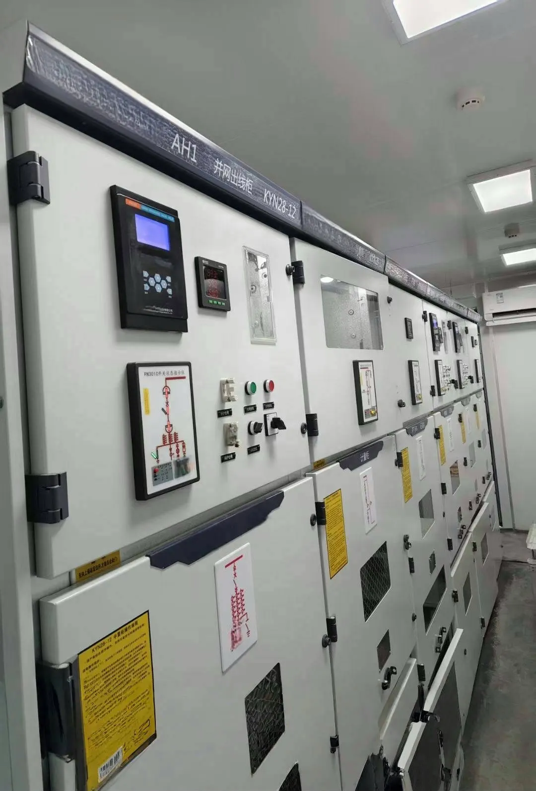
Current transformers (CTs) and voltage transformers (VTs), when installed, provide measurement signals for metering and protective devices. Protective relays process these inputs according to settings and logic; meters, indication lamps, auxiliary contacts and communications equipment support operation and monitoring. Buyers should distinguish features required by the single-line diagram from optional cabinet accessories.
| Component | Main role | Specification question |
|---|---|---|
| Circuit breaker | Interruption of rated currents and specified faults | What are the rated voltage, current and breaking duties? |
| Busbar | Current distribution between circuits | How is the bus arranged and rated? |
| CT / VT | Measurement signals | What ratios, classes and burdens are required? |
| Protective relay | Protection logic and trip signals | Which functions and interfaces are specified? |
| Controls and metering | Operation, status and monitoring | What indications and communications are required? |
Low-, Medium- and High-Voltage Switchgear Are Not the Same Product
Switchgear covers a family of designs rather than one universal cabinet. Low-voltage equipment commonly serves downstream building and industrial distribution. Medium-voltage assemblies often serve industrial feeders and utility-distribution circuits. High-voltage installations can involve different enclosure, interrupting, insulation and substation arrangements. The specific LV/MV/HV boundaries and applicable test standards depend on the project jurisdiction and standard system; a single global cutoff table would be misleading.
JSGK’s high-voltage switchgear page identifies KYN, XGN and related metal-enclosed cabinet families for receiving, distribution, protection, monitoring and measurement. Its low-voltage switchgear and distribution cabinets page provides a separate product route for downstream systems. Those pages identify product families, not a promise that all ratings or protection features are available in every configuration.
Air-Insulated and Gas-Insulated Designs
Insulation technology is another choice independent of voltage class. Air-insulated switchgear uses air as a principal insulation medium in the relevant design. Gas-insulated equipment encloses components in a controlled insulating-gas environment. Solid-insulated and hybrid approaches also exist; their applicability depends on equipment design and standards.
Space, rated electrical duty, maintenance access, environmental conditions and project requirements all affect the selection. It is not technically sound to claim that GIS is universally superior to AIS. For the relevant product family, JSGK provides a ring main unit and gas-insulated cabinet page; final insulation medium and cabinet features must be verified by the actual datasheet.
Where Does Switchgear Sit in a Power Distribution System?
A simplified distribution route may be: incoming supply → upstream HV or MV switching and protection → transformer where voltage conversion is required → LV switchgear → outgoing feeders and loads. Real topologies vary, and not every installation follows this exact sequence.
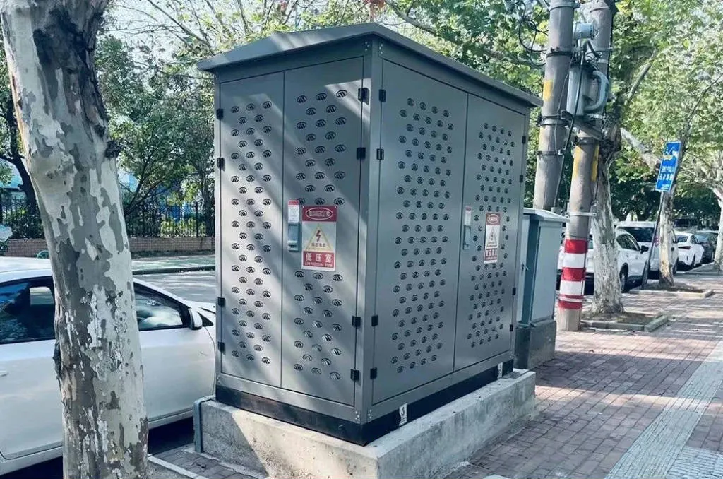
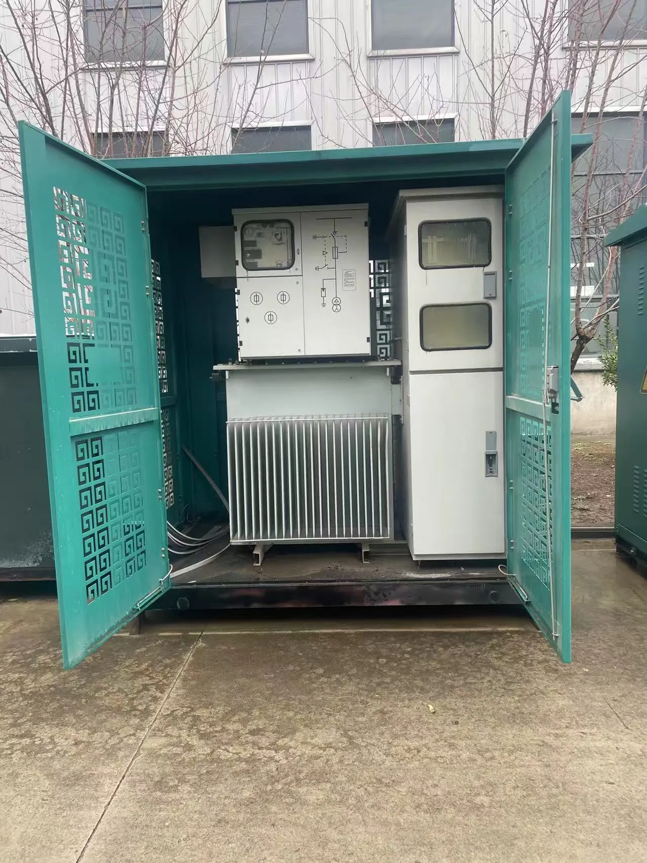
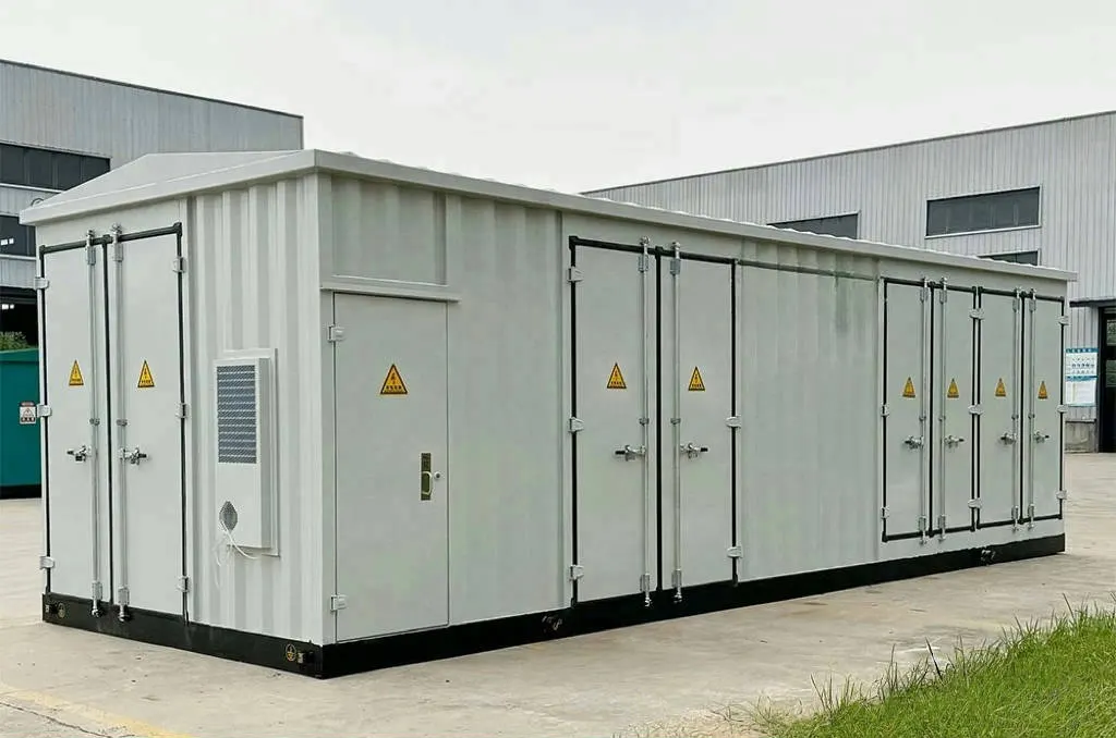
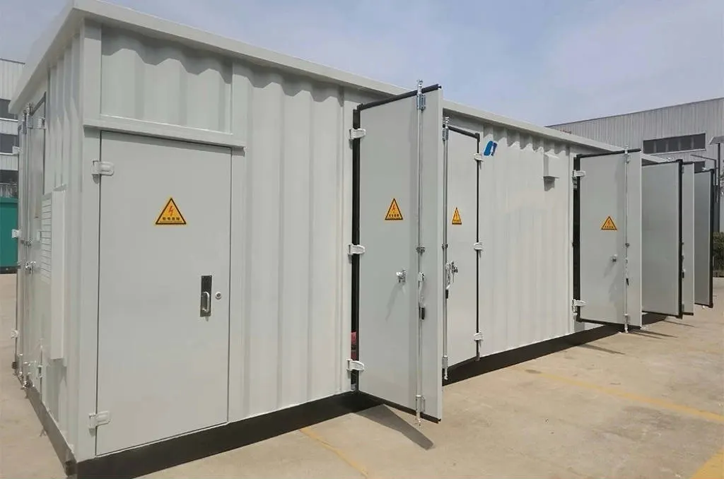
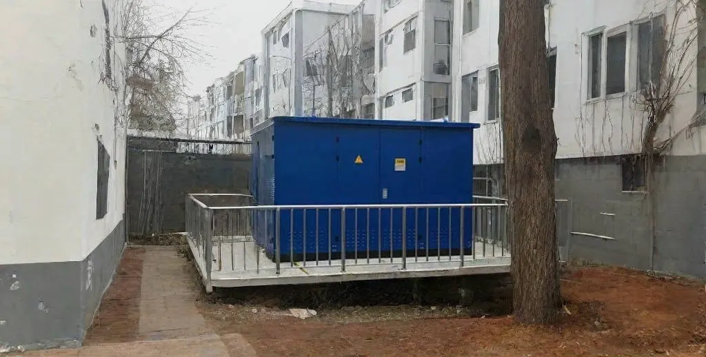
For example, a box-type substation can combine power transformation with higher- and lower-voltage switching and distribution functions within an integrated arrangement. JSGK’s box-type substation product page illustrates this system relationship. Switchgear and transformers do different jobs: the transformer changes voltage levels; switchgear controls, protects and isolates the circuits connected to it.
Switchgear vs. Switchboard: What Is the Difference?
Both terms describe power-distribution equipment, but they are not always interchangeable. In North American standards and procurement, low-voltage switchgear and switchboards can have different construction, device and standard requirements. Elsewhere, equipment terminology and classification may follow IEC-based or national specifications. Rather than assuming a name establishes performance, compare the agreed product standard, fault ratings, device types, compartment arrangement, access and maintenance requirements.
A panel labeled ‘switchgear’ should not be accepted solely by its name. Buyers should verify what is inside the assembly and what operating and testing duties the submitted design actually covers.
What Should a Buyer Specify Before Selecting Switchgear?
Knowing the basic switchgear definition is useful, but a meaningful electrical equipment quotation needs a project description. A buyer should normally prepare the following information for engineering review:
- Nominal system voltage and applicable voltage class.
- Rated current and incoming/outgoing circuit quantities.
- Available short-circuit level and required withstand or breaking ratings.
- Single-line diagram, bus-section arrangement and feeder scheme.
- Protection, metering, interlocking and communications requirements.
- Indoor or outdoor installation, ambient and site conditions.
- Cable entry, terminal interfaces and enclosure requirements.
- Operating and maintenance-access constraints.
- Applicable project standards and document requirements.
- Equipment quantities and required delivery interfaces.
These inputs help differentiate a general product-family inquiry from an approved cabinet configuration. JSGK requests voltage level, current, short-circuit level, circuit quantity, environment and drawings for project review. To continue from this explanation to actual equipment selection, discuss your switchgear requirements with JSGK and provide the relevant system information.
In summary, electrical switchgear is the system’s coordinated switching, protection and isolation equipment. Its components, insulation arrangement and rated performance vary with the circuit and project standards. Start with the function and single-line diagram, then evaluate the specific product family and confirmed technical configuration.