Inside a KYN Switchgear Line‑Up: Incoming, Outgoing, Protection and Metering, Panel by Panel
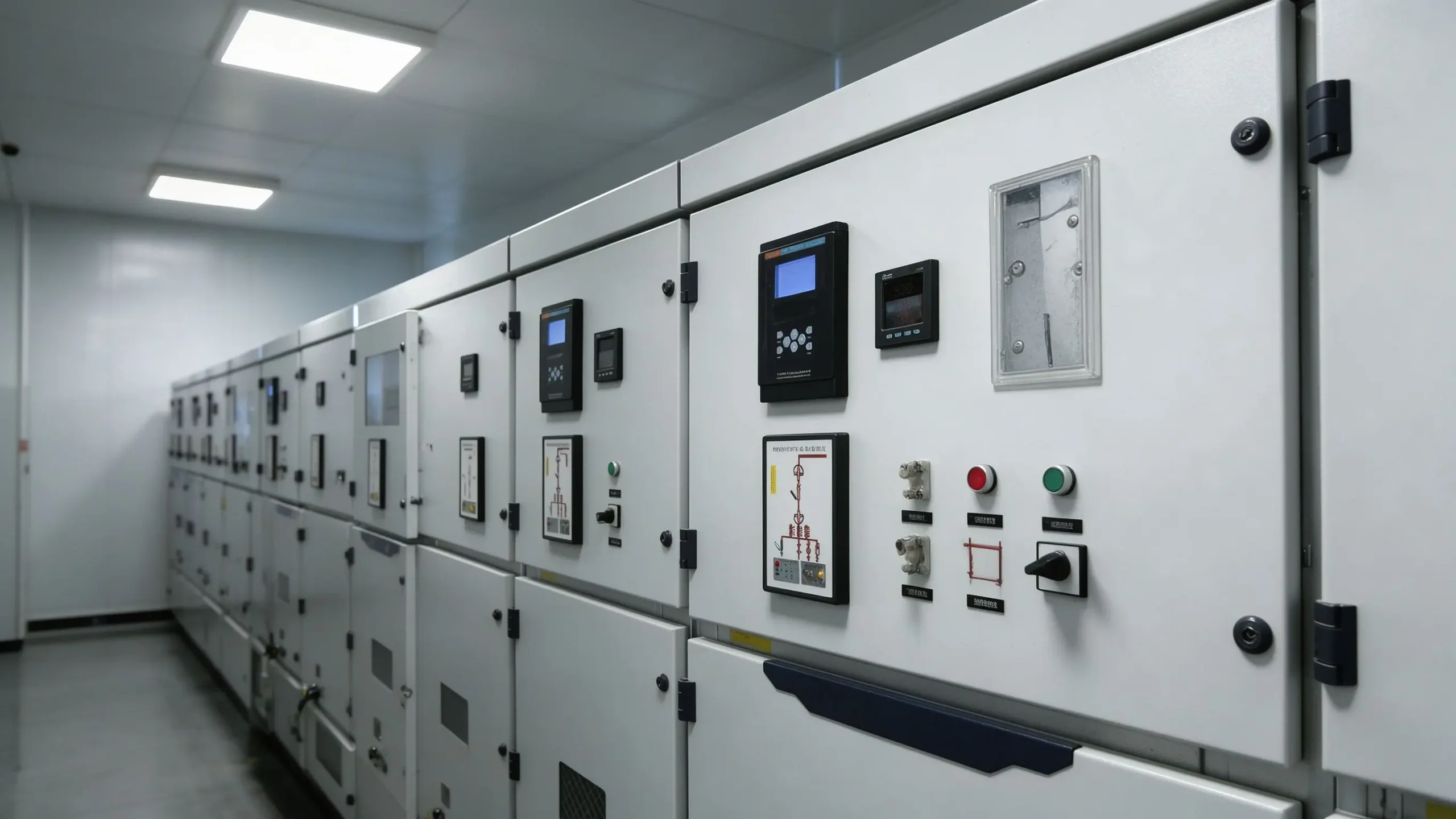
Open the door of a medium‑voltage switchgear room and the first thing you notice is repetition. Row after row of steel cubicles, each roughly the same width, each with a small control panel on the front and a mimic diagram telling you what the cubicle does. Repetition looks boring. It is not. That row is how a distribution room stays alive when a fault happens somewhere downstream.
JSGK supplies KYN, XGN and related metal‑enclosed cabinet families for receiving, distribution, protection, monitoring and measurement. This article explains what each position in the row actually does, how the front panel is arranged, and what we check before the cubicles leave the factory.
Why a room needs several cubicles, not one
A single incoming cable does not need a row. A real distribution room does. Power arrives on one or more incoming feeds, lands on a common busbar, and then leaves again through several outgoing feeders that go to transformers, motor control centres or ring nodes. Each of those jobs gets its own metal‑enclosed cubicle because each job carries a different duty and a different protection setting.
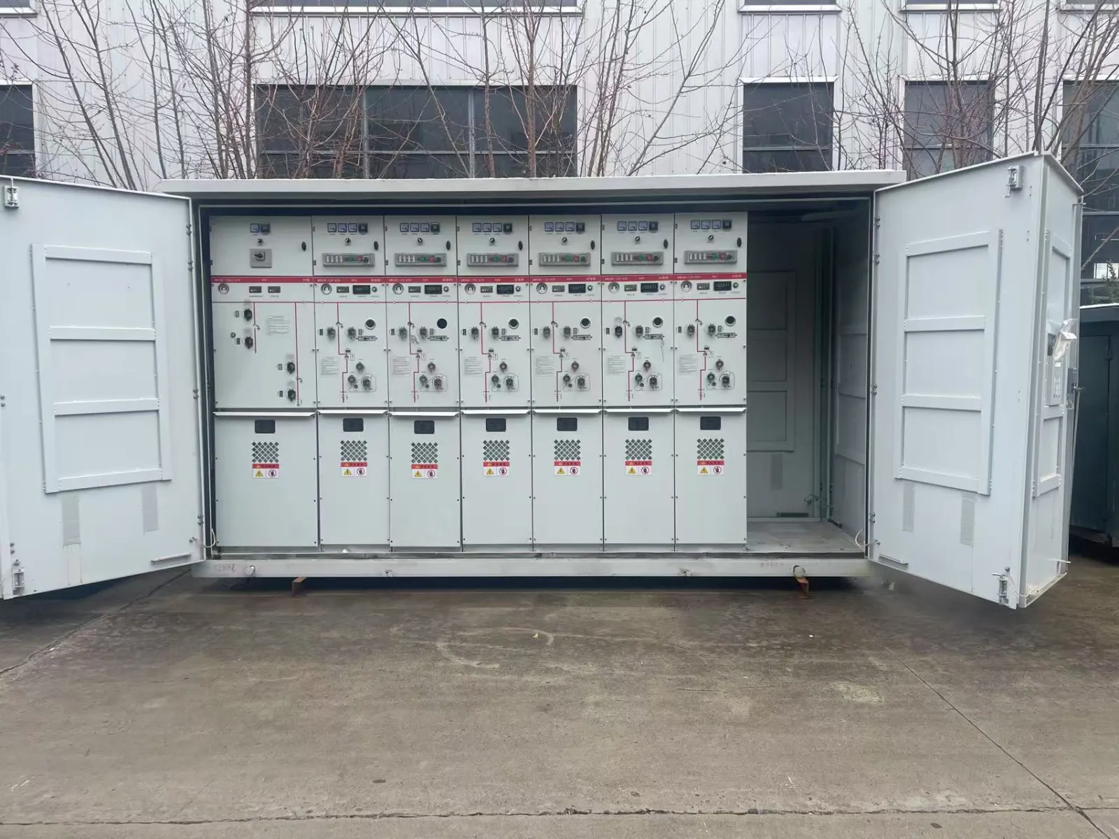
The line‑up is drawn on a single‑line diagram before a single cubicle is welded. That diagram names the incoming panel, the bus section, each outgoing feeder, the protection panel and the metering panel. On the shop floor, cabinet arrangement drawings fix the width, depth, front‑access clearance and cable‑entry position so the row fits your room.
The four positions you will meet
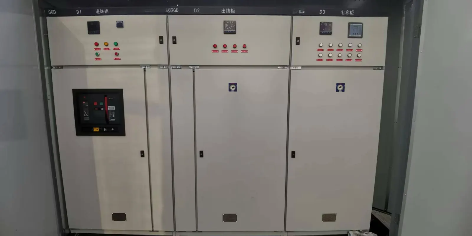
- Incoming (and bus‑section) panels. These receive the supply from the utility or the upstream transformer and connect it to the main busbar. A bus‑section panel splits the bus so two halves can run independently or in parallel.
- Outgoing panels. These carry power out to each load. A feeder to a transformer, a feeder to a motor, a feeder to a ring main unit, each is a dedicated outgoing cubicle with its own switchgear.
- Protection panels. These hold the protection relays that sense overcurrent, earth fault and other abnormal conditions and trip the relevant breaker before damage spreads. The relay settings are matched to the feeder, not copied across the row.
- Metering panels. These carry the measurement and metering instruments used to read voltage, current, energy and power, often feeding the utility billing or the plant energy system.
A smaller room might merge some duties into fewer cubicles. A larger one duplicates incoming and bus‑section positions for security. The single‑line diagram decides it.
What is actually on the front of the cabinet
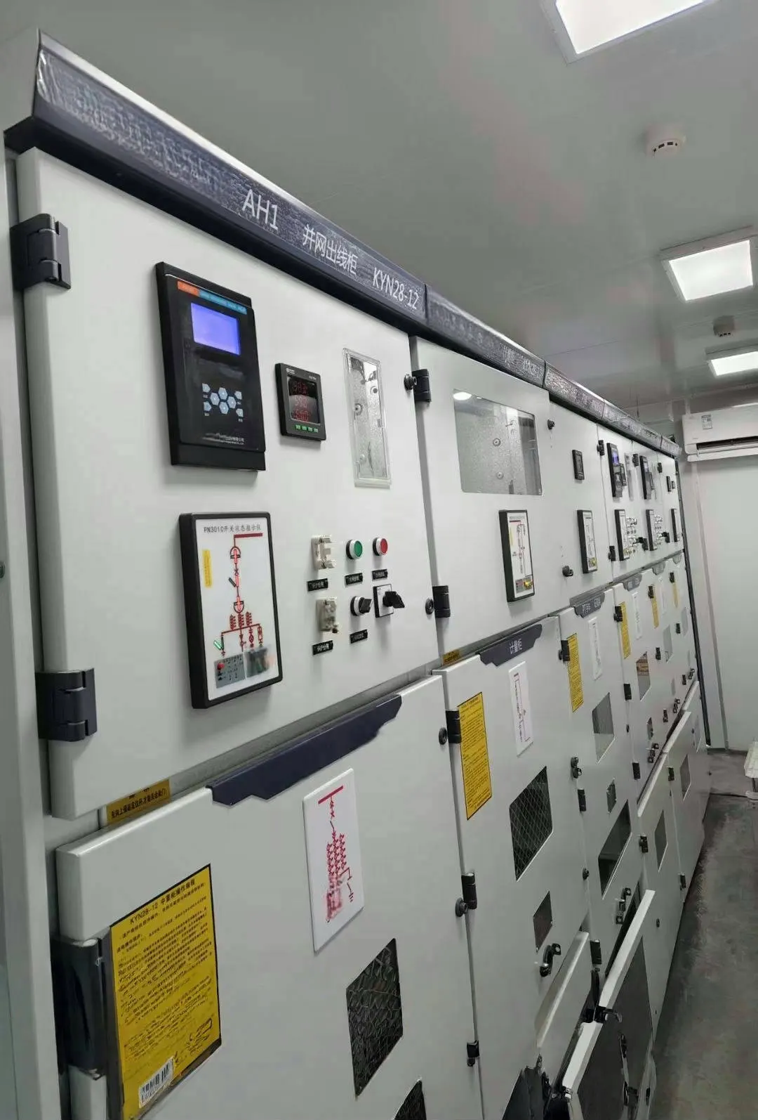
Stand in front of a KYN cubicle and the front panel is doing a job, not decoration. You will see a protection relay or controller with a small display and pushbuttons. You will see an analog meter or digital instrument for voltage and current. You will see indicator lights, control switches and the operating handle for the switching device.
Below the instruments, a mimic diagram shows the primary circuit in miniature: where the busbar runs, where the breaker sits, where the cable compartment exits. When an operator opens the cubicle, the mimic tells them, at a glance, whether that feeder is closed or tripped, without them touching anything. Interlocks, door shutters and earthing switches are arranged so a compartment cannot be opened while it is still live.
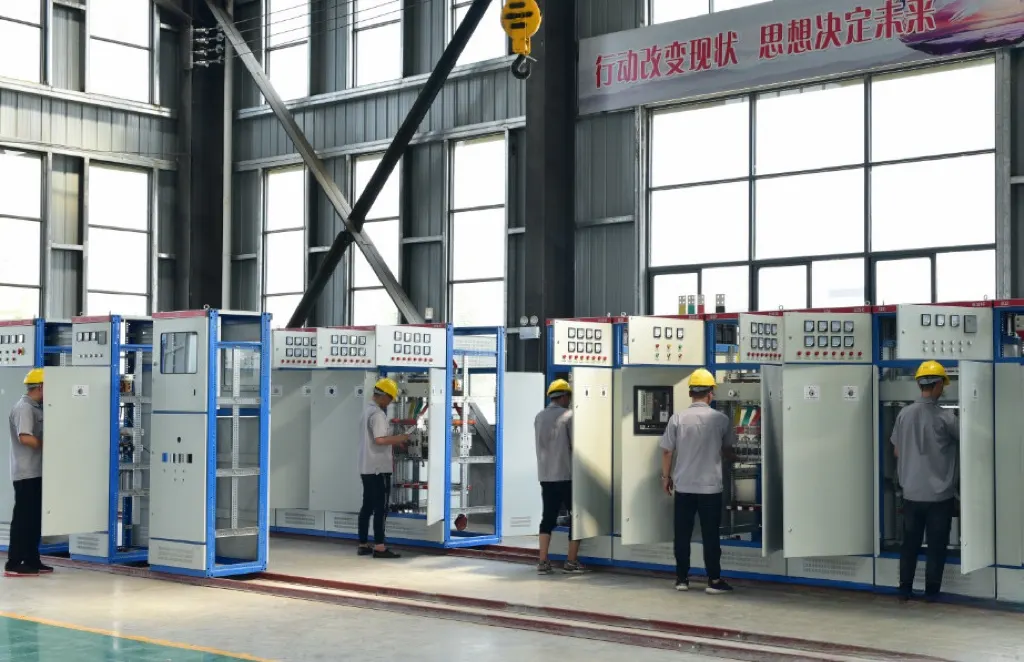
Inside, the cubicle divides into compartments: a breaker or switch compartment, a busbar compartment, a cable compartment and a low‑voltage or secondary compartment for the control and protection wiring. Separating them is deliberate. A fault in one compartment is contained by the metal barriers instead of arcing across the whole row.
When you walk a finished row, look for three things that separate a built‑to‑order line‑up from a generic one. The compartment doors should carry shutters that cover the live stubs when the breaker is withdrawn. Each cubicle should have a visible earthing switch or earthing point for the cable compartment before work starts. And the secondary door should open without releasing any high‑voltage interlock. These are the details that let a maintenance engineer work the feeder safely years after commissioning.
Circuit breakers, busbars and the secondary circuit
The switching element in the circuit compartment is a circuit breaker (or load‑break switch on simpler cubicles) that can make, carry and break load current, and trip automatically under fault current through the protection relay. The main busbar is the common conductor that ties the incoming panel to every outgoing panel; its rating is chosen to carry the full room current with margin.
The secondary circuit is the control, signalling and wiring between relays, instruments, pushbuttons and the breaker. It runs in its own compartment and is where most export defects hide. Neat, labelled secondary wiring matters as much as the copper, because a relay that trips the wrong feeder is expensive even when the main busbar is fine.
How the row protects the room
Put the pieces together and the protection story is simple. An outgoing feeder develops a short circuit. The current rises. The protection relay on that feeder sees the overcurrent and sends a trip signal to its own breaker. That breaker opens, clearing only the faulted feeder while the rest of the bus stays live. The incoming panel and the other feeders keep running. Without correctly graded relays and dedicated breaker per feeder, one fault would trip the whole room into darkness.
That grading of protection settings, feeder by feeder, is decided on the single‑line diagram and checked during assembly and secondary wiring.
Routine and outgoing inspection before shipping
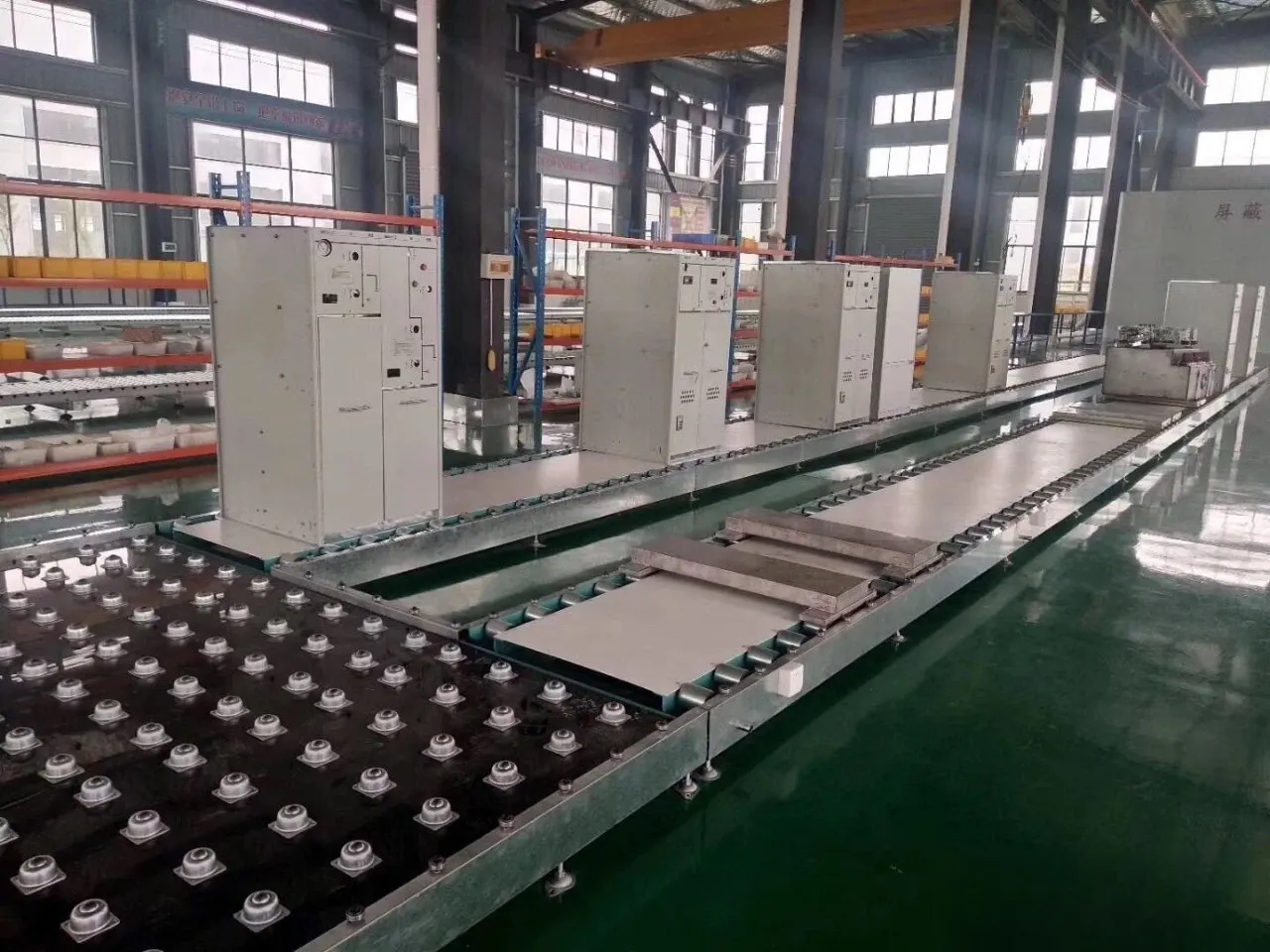
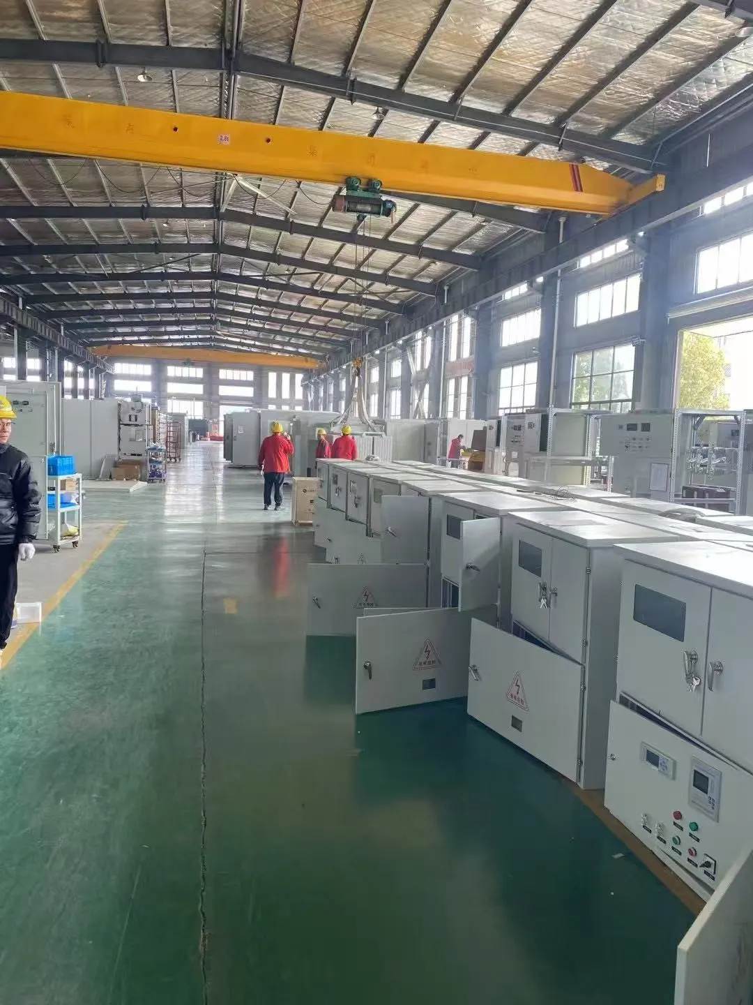
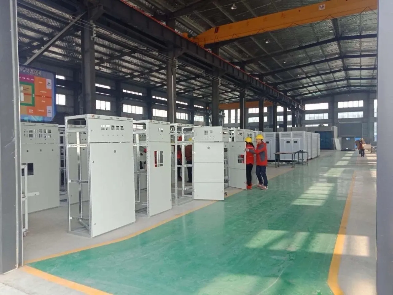
Two inspection gates sit between a finished row and the container. Routine inspection runs as the cubicles take shape, checking the build against the drawing. Outgoing inspection is the final pass: dimensional checks, a look at the coating, component inspection and a check that the secondary wiring and interlocks behave as the diagram says. Inspection records and test records are prepared with the order, so your site team and your independent inspector can read what was checked.
Final configuration is locked from approved datasheets, single‑line diagrams, cabinet arrangement drawings and project standards before production. Tell us the voltage level (10 kV and 35 kV classes are typical for this line), the rated current, the short‑circuit level, the number of outgoing circuits and the site environment, and we will lay out the row to fit your room.