
How Do Power Transformers Work?
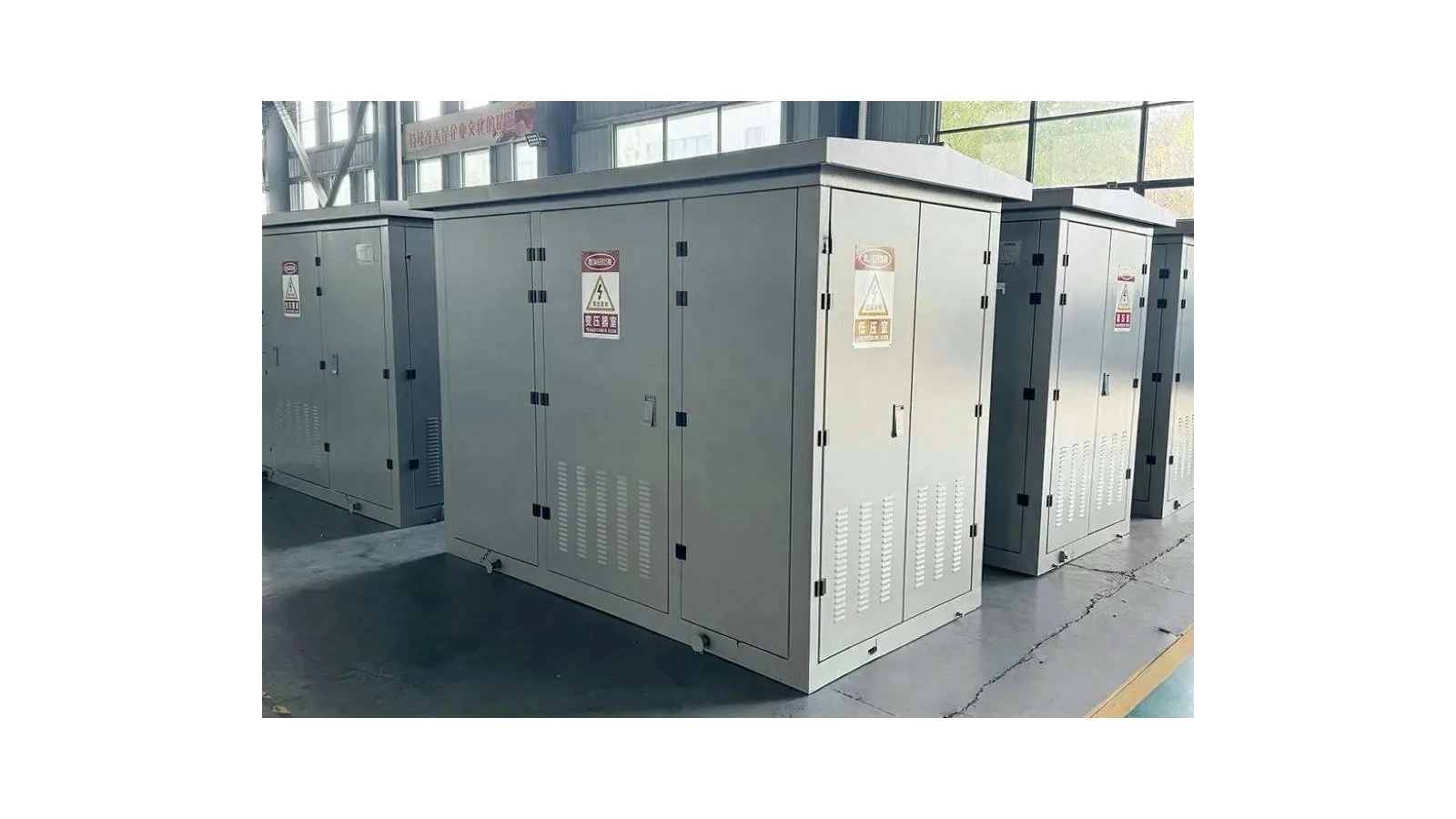
Power transformers transfer electrical energy through a changing magnetic field. An alternating voltage applied to one winding establishes alternating magnetic flux, which induces voltage in another winding linked by that flux. When a load is connected, current flows in the output circuit and the transformer draws the corresponding input power, together with its losses.
The winding turns relationship determines the basic voltage ratio. It does not create extra energy. This explanation uses a conventional AC, two-winding transformer as its starting point; practical designs add insulation, cooling and other features to keep that process within the equipment’s electrical and thermal limits.
How Alternating Voltage Creates Magnetic Flux
The winding connected to the source is called the primary winding. When AC voltage is applied, the magnetic flux changes continuously. In a conventional transformer, the magnetic core provides a path that links the windings and supports their electromagnetic coupling.
The sequence is easier to understand as a process: AC voltage is applied to the primary, alternating flux links the windings, and voltage is induced in the secondary. These are connected electromagnetic effects, not separate mechanical actions. There is no rotating generator inside a conventional power transformer.
The core’s role is magnetic. It is not a wire carrying the primary current into the secondary circuit. In an ordinary transformer with separate windings, energy is transferred through magnetic coupling while the insulation system provides the designed separation between circuits.
How Voltage Is Induced in the Other Winding
A winding linked by changing magnetic flux develops an induced voltage. The secondary winding therefore has a voltage at its terminals even before an external load draws current from it. Connecting a suitable load completes an output circuit and allows the transformer to supply power to that load.
This distinction separates voltage from delivered power. An energized secondary with no connected load can have voltage present without delivering useful load power. It must not be treated as safe simply because no appliance or circuit is drawing current.
“Primary” and “secondary” identify the input and output roles in the explanation. They do not automatically mean high voltage and low voltage. In a step-up application, the input winding operates at the lower voltage; in a step-down application, it operates at the higher voltage.
How the Turns Ratio Changes Voltage
In the ideal two-winding model, the winding voltage ratio follows the turns ratio:
V2 / V1 = N2 / N1
V1 and V2 are the primary and secondary winding voltages; N1 and N2 are the corresponding numbers of turns. More secondary turns give a higher secondary voltage. Fewer secondary turns give a lower voltage.
For a purely illustrative ideal transformer, a 2:1 primary-to-secondary turns ratio would reduce 200 V across the primary winding to 100 V across the secondary. This is a teaching example, not a JSGK product rating or a design recommendation.
Step-Up and Step-Down Operation
| Relationship | Voltage result | Meaning |
|---|---|---|
| More secondary turns than primary turns | Higher secondary winding voltage | Step-up operation |
| Fewer secondary turns than primary turns | Lower secondary winding voltage | Step-down operation |
| Equal turns | Equal ideal winding voltages | No nominal voltage change in this simplified model |
Real terminal voltages are affected by impedance, loading and operating conditions. For a three-phase transformer, the relationship between winding voltages and line voltages also depends on the winding connections. Do not apply a single-phase winding formula directly to line-to-line ratings without checking the connection arrangement.
What Changes When a Load Is Connected?
When the secondary supplies a load, secondary current produces a magnetic effect that is opposed by an additional component of primary current. The transformer draws more input current as needed to supply the load, subject to its ratings and operating conditions.
The load determines how much current is requested; the transformer’s nameplate rating is a limit under specified conditions, not a current that it forces into every connected circuit. A lightly loaded transformer does not continuously deliver its full rated output.
| Condition | Secondary side | Primary side |
|---|---|---|
| Energized with no external load | Voltage may be present, with no external load current | Excitation current and real no-load losses remain |
| Supplying a load | Load current flows according to the connected circuit | Input current includes the demand needed to supply the load |
Why Higher Voltage Does Not Create Extra Power
In an ideal transformer, input and output power balance. Increasing voltage corresponds to a lower current for the same transferred power and comparable power-factor conditions. Actual output power is less than input power because real transformers have losses.
Transformer capacity is commonly expressed in kVA or MVA, which describe apparent power. These values should not be treated as identical to kW or MW without considering power factor. A voltage ratio alone is insufficient to calculate a project’s required transformer capacity.
Why Real Transformers Have Losses and Temperature Limits
Current flowing through winding resistance produces heat. Alternating magnetic flux also produces core losses, including hysteresis and eddy-current effects. Other losses depend on the design and operating conditions.
Some losses remain while the transformer is energized with little or no load; others increase with loading. This is why a practical transformer cannot be represented only by an ideal voltage-ratio equation.
Cooling removes heat so the equipment can operate within its specified temperature limits. It does not eliminate electrical losses or make unlimited loading possible. The allowable duty depends on the actual transformer, its cooling arrangement and its environment. No single efficiency or temperature-rise figure applies to every power transformer.
Do Dry-Type and Oil-Immersed Transformers Work Differently?
Both families use electromagnetic induction. Their important differences concern how the active assembly is insulated, cooled and installed, rather than a different fundamental method of changing voltage.
A dry-type transformer uses its specified solid-insulation and air-related cooling arrangement. An oil-immersed design uses insulating liquid alongside solid insulation, with a design-specific means of transferring heat. The particular materials, enclosure and cooling equipment must be checked in the approved technical documents.
The JSGK transformer overview references dry-type and oil-immersed families as supporting equipment for integrated electrical projects. These references help frame a selection discussion; they are not a verified catalogue of standalone JSGK transformer manufacturing models.
What This Means for a Substation Project
Understanding the process helps explain why project specifications ask for voltage, frequency, capacity, connection arrangement and cooling conditions. Each describes a different part of the required operating duty.
- Input and output voltages: define the electrical interface on each side.
- Frequency: must match the equipment’s intended operating conditions.
- Capacity: establishes the required load duty under specified conditions.
- Connections: affect the system interface, including three-phase relationships.
- Cooling and environment: influence the permitted thermal operating duty.
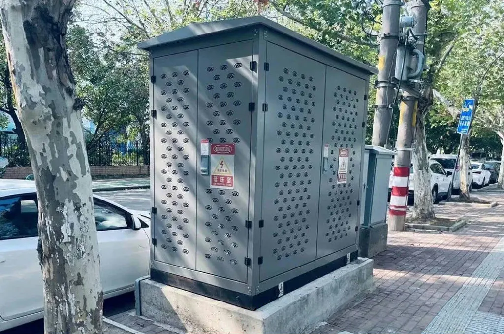
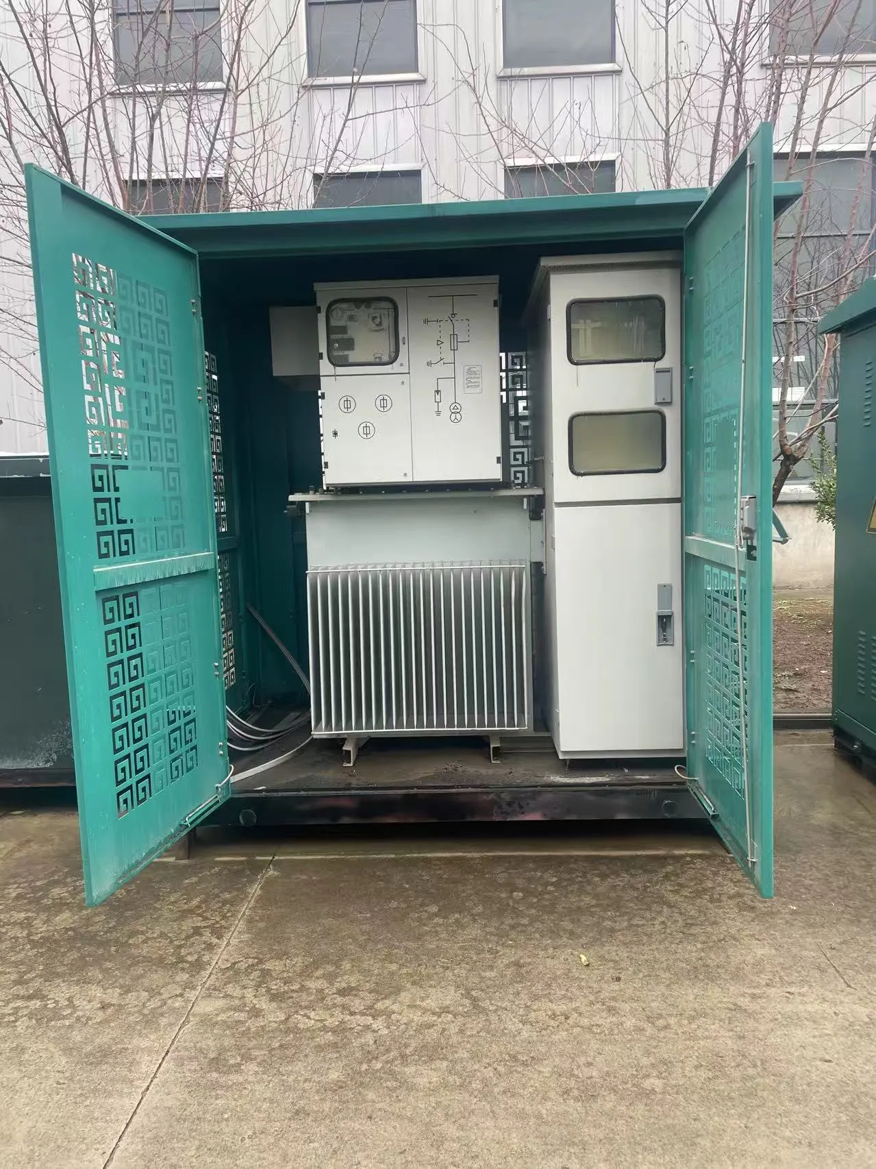
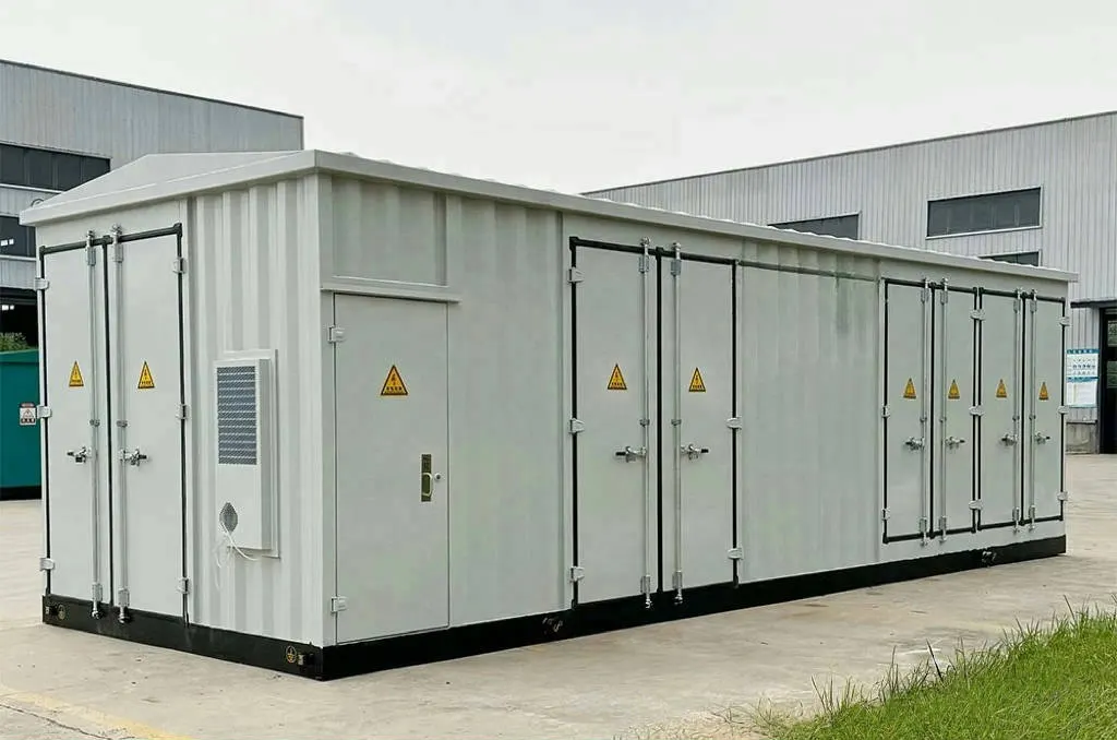
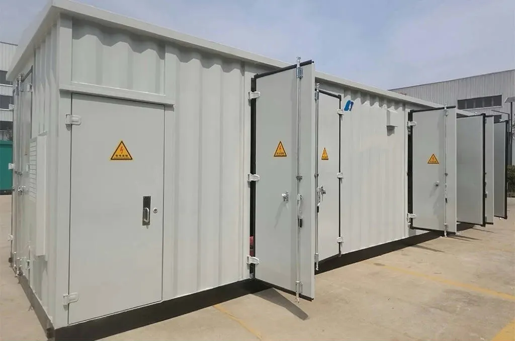
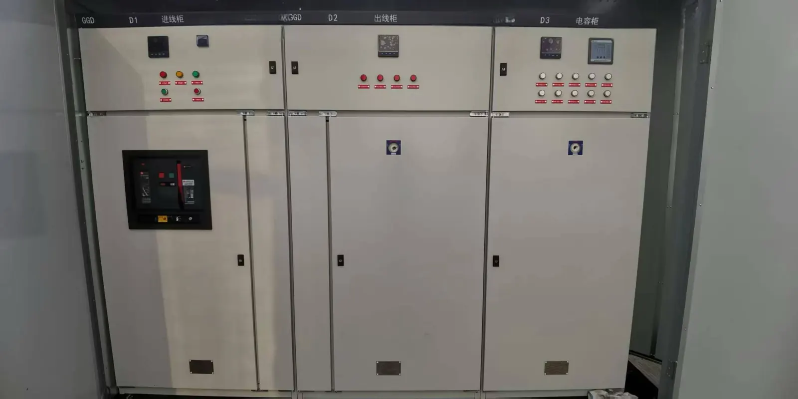
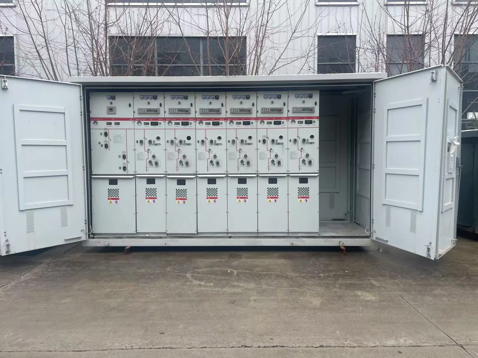
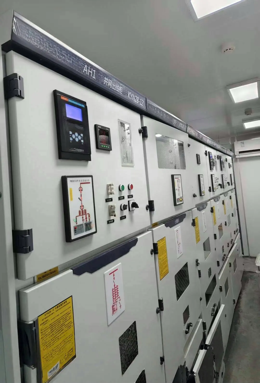
JSGK’s box-type substation configuration places transformer requirements alongside high- and low-voltage cabinets, the enclosure and auxiliary systems. The transformer transfers energy between voltage levels; the surrounding equipment provides its own switching, protection and distribution functions.
Frequently Asked Questions
Can a Conventional Power Transformer Operate on Steady DC?
It cannot be supplied with steady DC in the same way as its rated AC supply. Steady DC does not provide the continuing alternating flux needed for normal operation and can cause damaging current. This does not mean transformer-based electronic converters cannot use a DC source; such converters create a changing waveform through switching circuitry.
Does a Transformer Change Frequency?
A conventional AC transformer does not convert supply frequency. Voltage transformation is different from frequency conversion.
Are All Transformers Electrically Isolated?
No. Separate-winding designs and autotransformers have different circuit arrangements. Do not infer galvanic isolation from the word “transformer” alone; check the actual design.
Connect the Principle to the Required Duty
A power transformer works through changing flux, induced voltage and load-dependent energy transfer. Its actual performance depends on the design and operating conditions. For an integrated distribution project, discuss your voltage, capacity and system-interface requirements with JSGK using the project single-line diagram and approved technical requirements.