What Do Power Transformers Do in Electrical Power Systems?
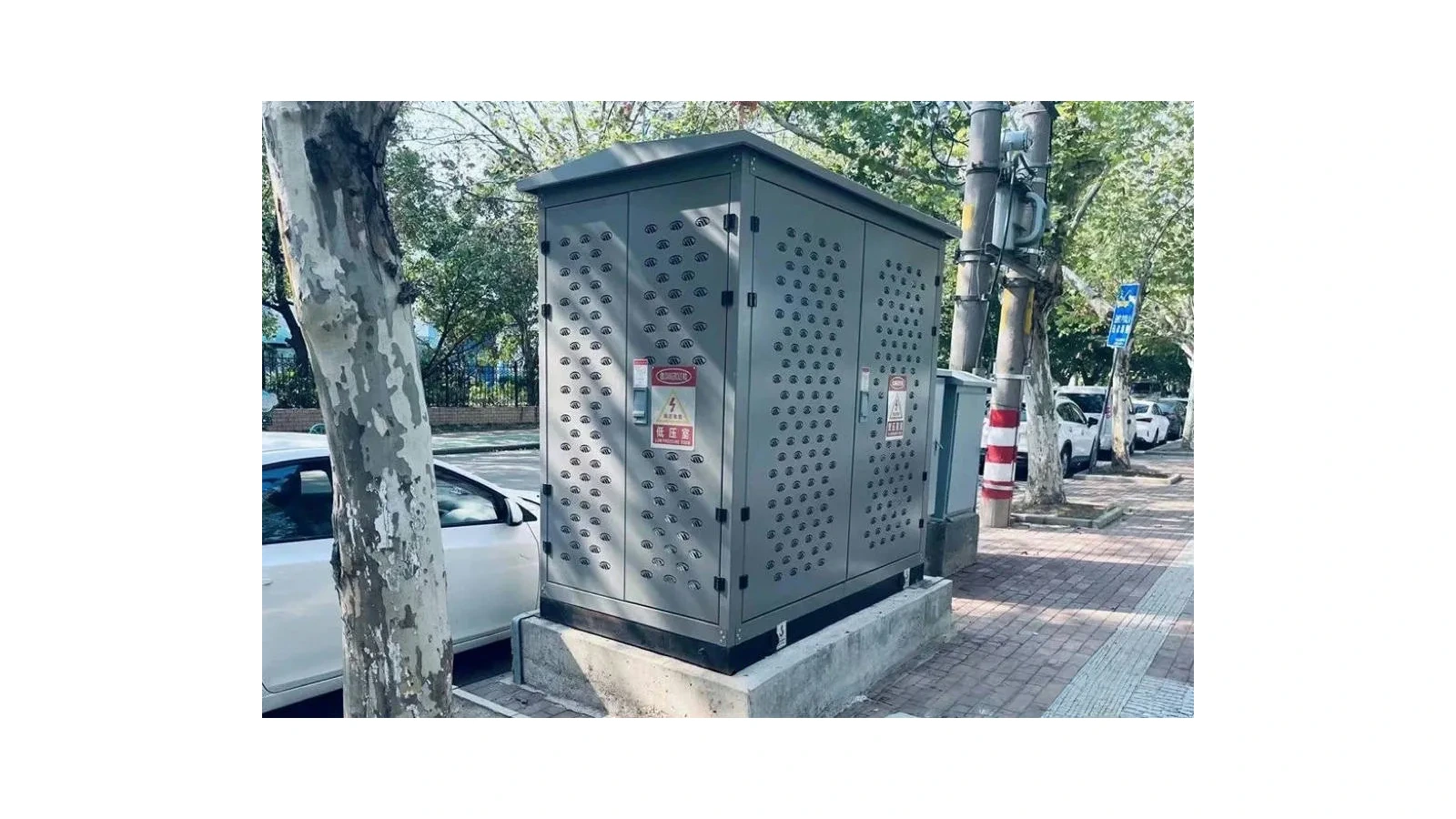
Power transformers transfer electrical energy between system circuits, commonly at different voltage levels. They allow electricity to move from generation into transmission networks, between network voltage levels and toward distribution systems and facility loads. The task depends on where the transformer is installed and how the system is designed.
They do not generate electricity or replace the complete set of switching and protection equipment around them. To understand what power transformers do, follow the electricity through the system and identify the voltage interface at each stage. This article focuses on those system roles rather than the internal electromagnetic process.
Where Do Transformers Fit in the Electricity Supply Chain?
A typical supply path includes generation, transmission, substations, distribution and the final load. Transformers can appear at several points because the voltage suited to one stage is not necessarily suited to the next.
A simplified sequence is: generator output, voltage step-up, transmission, network voltage transformation, local distribution and customer equipment. Actual systems vary. An industrial site may receive power at a higher voltage and operate its own distribution transformers, while another customer receives an already reduced supply voltage.
Reading the system in this order helps distinguish a transformer from an entire substation. The transformer performs an assigned electrical task within the station; it is not a substitute for every device, cable and control interface represented on the single-line diagram.
Step Up Voltage for Power Transmission
At a generation connection, a generator step-up transformer can raise the generator’s output voltage to the required transmission level. For the same transferred power and comparable phase and power-factor conditions, higher voltage means lower current.
This matters because resistive losses in a conductor depend on current squared times resistance, commonly written as I²R. Reducing current can therefore reduce those conductor losses when the comparison holds the relevant conditions constant.
The transformer itself still has losses, and a transmission system has other design constraints. Higher voltage is not a universal instruction to keep increasing voltage without limit. Insulation, clearances, switching equipment, network standards and cost must all be considered. No fixed energy-saving percentage follows from the word “step-up.”
Connect Different Network Voltage Levels
Transmission and subtransmission networks may use several voltage levels. Transformers at system interfaces transfer power between them so different sections can operate at their planned voltages.
At a receiving station, the assigned role may be to reduce the incoming transmission voltage for a downstream network. A network interconnection can have a different purpose and operating arrangement. The role should be read from the system design rather than inferred from the size of the tank or its appearance.
| Position | Main task | Key interface to identify |
|---|---|---|
| Generator connection | Match generator output to the required network voltage | Generator and transmission-system requirements |
| Network substation | Connect planned network voltage levels | Incoming and outgoing system specifications |
| Distribution or facility supply | Provide the voltage needed by the next distribution stage | Supply voltage and downstream circuit requirements |
These are functional examples, not statements about a particular supplier’s available ratings. The JSGK transformer selection references address supporting transformer inputs for integrated substation and distribution projects. They should not be interpreted as evidence that every large transmission-transformer design is part of a verified JSGK manufacturing range.
Supply Distribution Networks and Facility Loads
Closer to the point of use, transformers can reduce voltage for local distribution or facility circuits. A factory may need different supply interfaces for its incoming network and internal loads. Commercial or campus distribution can likewise involve several coordinated stages.
The useful question is what voltage and load duty the next stage requires. A transformer selected for one facility cannot be assumed suitable for another merely because both sites are described as industrial.
Power Transformers and Distribution Transformers
The terms describe equipment in different technical and application contexts. Power transformers are often associated with bulk network transfer, while distribution transformers serve downstream distribution duties. Exact classifications depend on the applicable definitions, standards and market context.
The underlying voltage-transformation principle is related, but this does not make all designs interchangeable. This article uses the supply chain to explain their roles; it does not set a universal capacity boundary between the categories or establish that a distribution-equipment supplier manufactures large grid transformers.
What Does the Transformer Do Inside a Box-Type Substation?
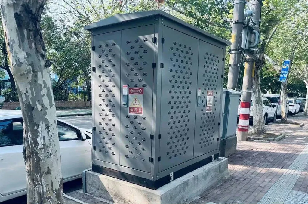
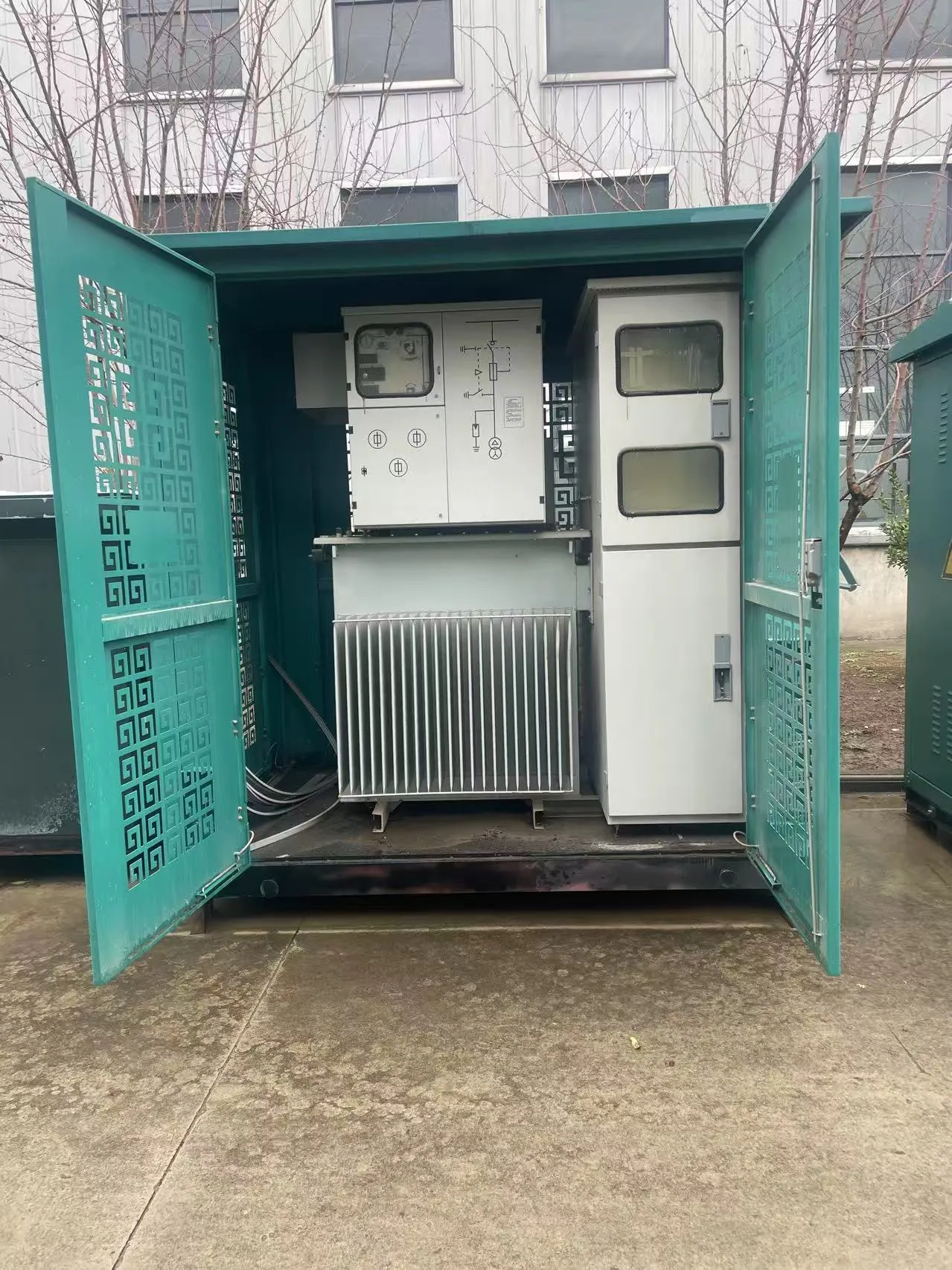
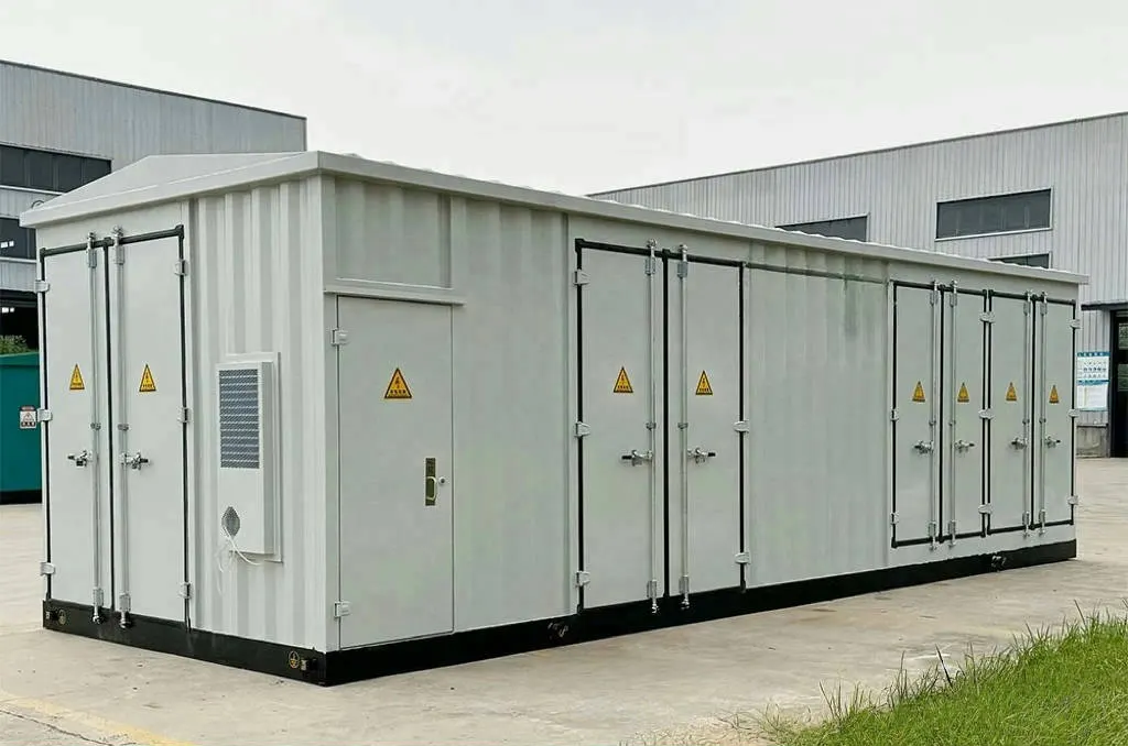
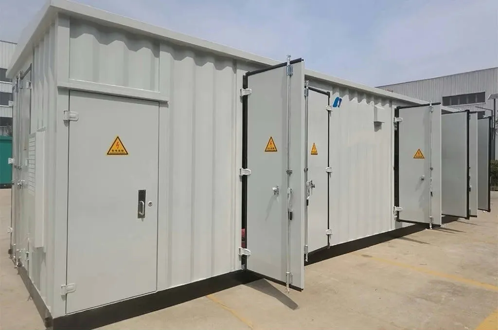
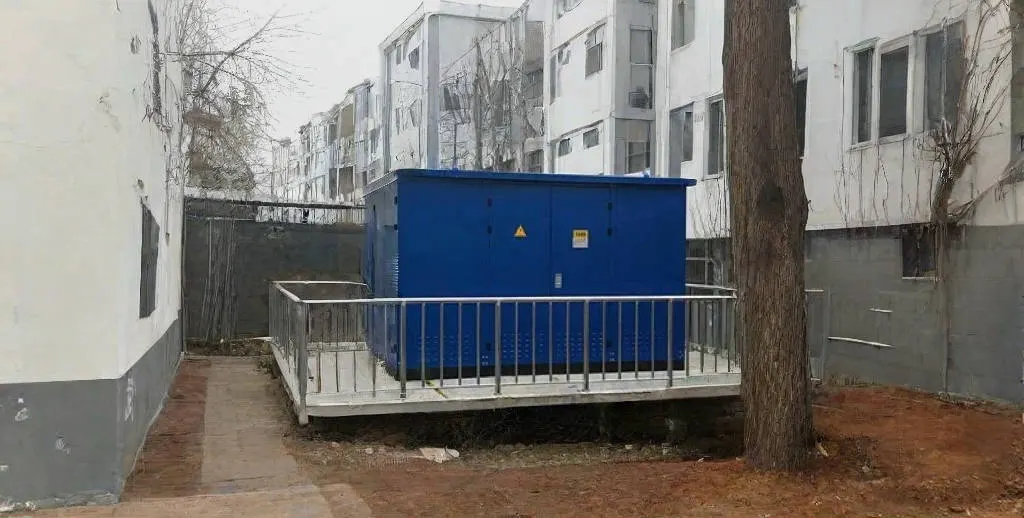
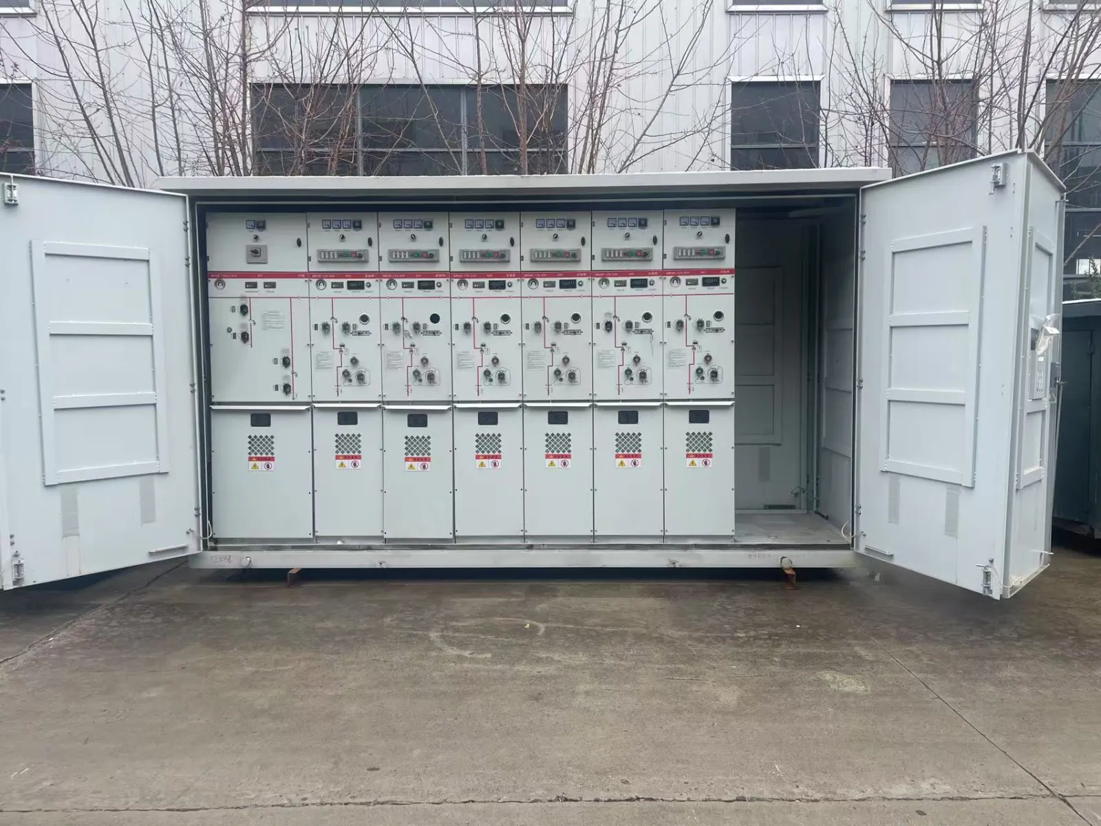
In a box-type substation, the transformer is part of an integrated arrangement rather than the whole system. JSGK’s box-type substations page describes a combination of transformer, high-voltage cabinet, low-voltage cabinet, enclosure and auxiliary systems.
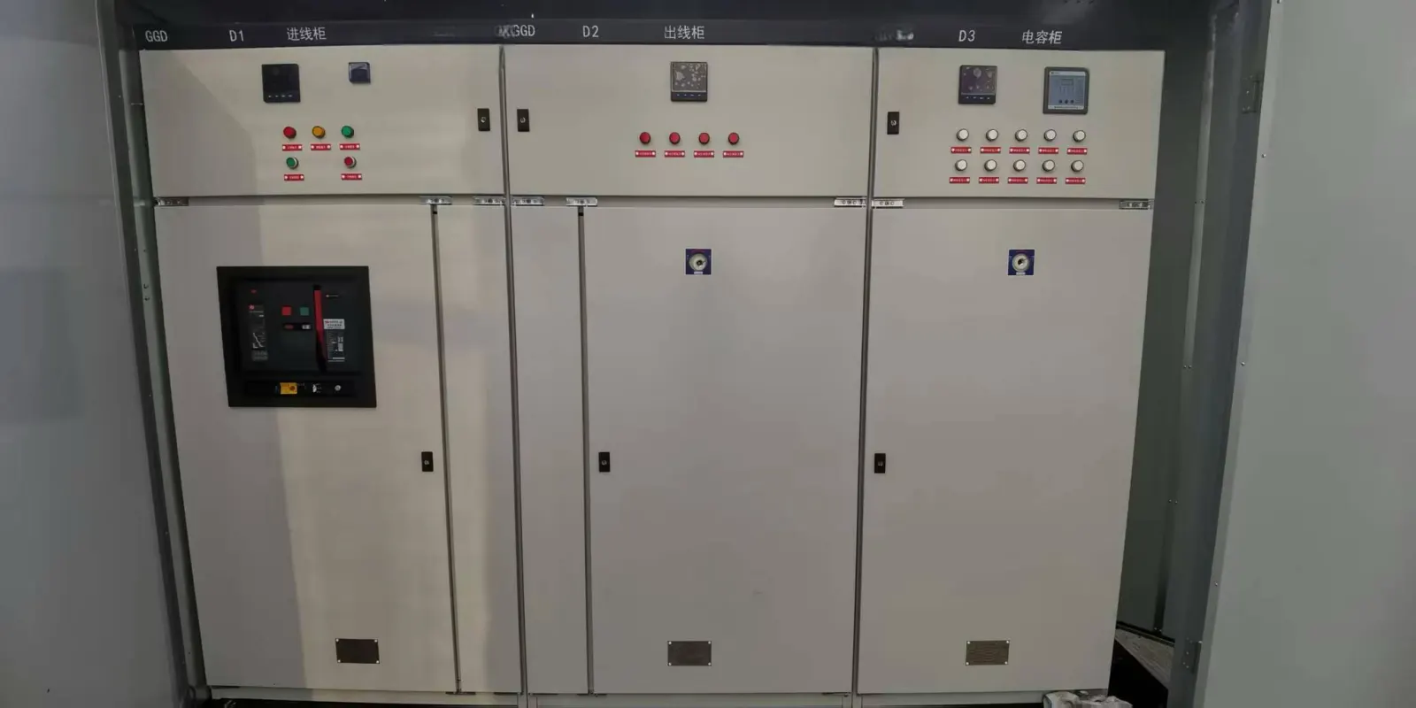
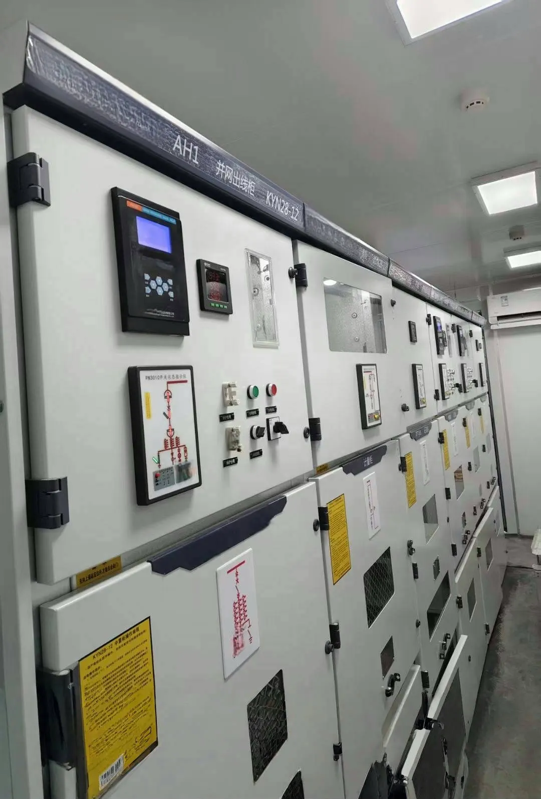
The transformer provides the required voltage interface. Incoming switching and protection depend on the specified high-voltage scheme; the low-voltage assembly distributes power to outgoing circuits and provides the functions included in its design. The enclosure and internal layout must accommodate the approved equipment and its installation conditions.
| Part of the arrangement | Function to establish | What requires project confirmation |
|---|---|---|
| Transformer | Voltage transformation and power-transfer duty | Voltage, capacity, connections, impedance and thermal requirements |
| Incoming cabinet | Switching and protection functions in the selected scheme | Devices, ratings and coordination |
| Outgoing distribution cabinet | Supply the intended downstream circuits | Circuit arrangement, ratings and specified protective functions |
| Enclosure and auxiliaries | Accommodate the equipment and required site interfaces | Ventilation, access, cable entry and environmental conditions |
This is a functional explanation, not an installation drawing. The actual single-line diagram, equipment schedule and approved arrangement define which devices are included and how they interact.
What Does a Power Transformer Not Do?
Some expectations belong to other equipment or depend on a particular transformer design. Clarifying them prevents an incomplete system specification.
- It does not generate energy. A transformer transfers supplied energy and has its own losses.
- It is not a conventional frequency converter. Changing voltage is different from changing the supply frequency.
- It does not replace circuit protection. Breakers, relays, fuses and other devices have their own roles in the selected scheme.
- It does not guarantee a perfectly constant output voltage. Loading, impedance and any specified regulating arrangement affect the result.
- It does not always provide galvanic isolation. Separate-winding and autotransformer arrangements differ.
A transformer may have monitoring, protection interfaces or voltage-adjustment equipment as part of its design. Those features must be specified; they should not be assumed from a generic transformer symbol.
Which Project Requirements Define Its Actual Role?
Start with the project single-line diagram and identify the source side, the load side and the boundary the transformer must connect. This gives a clearer starting point than requesting a capacity without explaining the system.
- Voltage levels: identify the incoming and required outgoing ratings.
- Capacity and duty: describe the load and operating requirements for engineering review.
- Frequency and phase arrangement: establish the system conditions.
- Connections and grounding: confirm the required electrical interface through the project design.
- Impedance and protection interfaces: coordinate with the wider network requirements.
- Installation conditions: record environment, cooling, space and connection constraints.
These inputs help define the task, but they are not a substitute for engineering selection. Protection settings, fault studies and detailed equipment ratings require the applicable project calculations and approved documents.
Match Transformer Requirements with the Surrounding Equipment
A transformer that has the required voltage ratio still needs compatible upstream and downstream equipment. Cabinet ratings, cable connections, protection coordination and physical layout all need to match the approved scheme.
For an integrated station, review transformer requirements alongside the switchgear arrangement rather than treating each item as an isolated purchase. A change in transformer configuration can affect terminals, clearances, heat removal and the enclosure layout; a change in the system scheme can also change the transformer requirements.
JSGK’s project route connects supporting transformer specifications with substations and distribution equipment. The appropriate deliverable is a confirmed equipment scope and technical interface, not an assumption that a product overview guarantees every rating, accessory or complete-network service.
Frequently Asked Questions
Do Power Transformers Generate Electricity?
No. They transfer energy from an electrical source to another circuit or system level. Their output is supplied from the input, with losses in real operation.
Does Every Substation Use the Same Transformer Configuration?
No. The required network connection, voltages, capacity, duty and installation conditions differ. Use the project scheme to establish the correct configuration.
Can a Transformer Replace Switchgear?
No. Voltage transformation and circuit switching or protection are different functions. The complete station needs the devices and coordination specified by its design.
Define the System Task Before the Equipment Package
Power transformers make different voltage levels work together across the electricity supply chain. Their particular role follows from the network position and the downstream requirement. For a JSGK distribution project, share your single-line diagram and electrical requirements with JSGK so the supporting transformer inputs and surrounding equipment scope can be reviewed together.